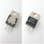
If it looks like a Liberty Bell it’s a real ST.
And that one is pretty old, judging by the oxidation. One cannot fake the effects of time.
And that one is pretty old, judging by the oxidation. One cannot fake the effects of time.
Good, I got one this and one Motorolla.
Will do the power supply repair and temporary heatsinks today.
Will do the power supply repair and temporary heatsinks today.
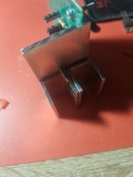
What I usually do with L profile is what I did in post 200, but that would require the other lead forming option for 5 pin TO-220’s. You just needs to use something that works mechanically. It’s only a handful of watts of heat removal. Running on +/-25 volt supply things would be getting toasty and you’d have to think about it more and minimize the number of interfaces. Here you just won’t. Run it for a while at volume and you’ll get a feel for how much heat sinking is needed. I don’t think you will have a problem with it here.
It seems, your source is reliable.
I did it. It works, but I can't realy test it right now as my baby is sleeping... Apartment all of the sudden became too small 😆.
I'm listening to it at low volume, so far I can say that it sounds very clear, nice sound, but it can predict a phone call :S ... nothing a little shielding couldn't fix I suppose.
And I still need to do mains filtering -I can hear a light switch, but there is no hum, zero.
I have it on for about half an hour now and it's nicely warm.

LM1875 will tolerate up to +/- 32V, but it does say +/- 25 in the data sheet...and that output level may damage your speaker.
You can remove sil-pads from old computer SMPS, or make thre to four layers pad using Teflon plumbing tape, with thermal grease as the sticky film.
Here I get kits with teflon bush, screw + nut and mica insulator for different sizes at the electronics market, in a small packet, just say size or device name...
#200; Thats a great idea. I will redo the power supply as I need another 8v reg anyways and will use L profile as so, but I"ll wait a bit... I'm almost getting to the point where I will put all boards inside the chassis to do the arangement and will see how it goes with the space. Plus I still need 5v, but that will be smps.What I usually do with L profile is what I did in post 200, but that would require the other lead forming option for 5 pin TO-220’s. You just needs to use something that works mechanically. It’s only a handful of watts of heat removal. Running on +/-25 volt supply things would be getting toasty and you’d have to think about it more and minimize the number of interfaces. Here you just won’t. Run it for a while at volume and you’ll get a feel for how much heat sinking is needed. I don’t think you will have a problem with it here.
Will just order them, too bad I trown away my scrap PSUs when I was moving...LM1875 will tolerate up to +/- 32V, but it does say +/- 25 in the data sheet...and that output level may damage your speaker.
You can remove sil-pads from old computer SMPS, or make thre to four layers pad using Teflon plumbing tape, with thermal grease as the sticky film.
Here I get kits with teflon bush, screw + nut and mica insulator for different sizes at the electronics market, in a small packet, just say size or device name...
I had tested it at higher volumes and it's really nice. Alot of lows, but still clear sound.
I connected 3.9 ohm 5w resistor as dummy load, o-scope and DMM, but I can't get the reading, DMM reads 1vpp ac @1khz sine, 1.5vpp ac @500hz sine...
Useless... o-scope reading is also useless (China... Vpp and Vrms changes as you change V/div).
It's like realy loud at 20% volume, but DMM shows 0.2vpp there...
But I can tell that at 1khz it doesn't start clipping even at full volume @1khz... really good, @500hz it starts clipping above 85% volume...
That is from Asus PC soundard... it has high output.
I think that I managed to get the o-scope to actually show correct Vpp.
10.7Vpp @500hz, just before clipping... = 3,6W, thats spot on
4.5Vpp @2khz, no clipping, full volume.
10.7Vpp @500hz, just before clipping... = 3,6W, thats spot on
4.5Vpp @2khz, no clipping, full volume.
Last edited:
Connecting preamp and amp to 1 psu... Should I do star grounding and also connect +- in same pattern? or can I connect psu -->preamp --> amp?
Also for avoiding ground loop... I think that I should connect signal gnd (between preamp and amp) only at one end (just for shielding of the wire)?
Also for avoiding ground loop... I think that I should connect signal gnd (between preamp and amp) only at one end (just for shielding of the wire)?
Last edited:
Will include LPF.
Wiring I did as mentioned.
I tested everything together and it is not good. It is clipping, amp is much warmer. Closing (CCW)100k pot introduces buzz, while opening (CW) 500k pot introduces sinewave. Input impedance of amp probably affecting preamp feedback loop I suppose? On the amp input I have 1uF and after that 22k to the gnd...
Last edited:
Thank you, I noticed that.
I have the preamp made, but I have above mentioned problems when connecting amp & preamp together.
To have custom eq curve preamp made was my initial idea, but later we adapted original feedback loop for tone controls as it was originaly in the radio, used NE5532 to drive it. So I have the preamp that sounds good, I just need to make it work with the amp.
- Home
- Amplifiers
- Solid State
- Amplifier suggestion for old 3w speaker
