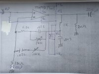
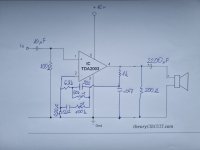
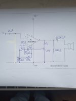
Is this correct for split supply for TDA2030?The original power supply is just the positive half of a split supply. What to do depends on the voltages you need, and the transformer(s) available.
Output cap needs to be something “big”. Just make it bigger than what was there and all is good. If you have a 2200, use it. Resistor from + input to ground isn’t critical. Just use the one from the data sheet of the chip you use. Input cap, 10 uF is fine. You probably have some.
If using a single supply with a split supply chip, use a 10k+10k voltage divider to make the bias reference, and bypass the lower cap with 100 uF. That will keep the 1/2Vcc reference noise and hum free. Hang the input resistor to that point. Then capacitor-couple the resistor from minus input to ground to keep the DC gain at 1. 100 uF is enough, more can’t hurt.

Ok, input resistor is not needed with split supply (also per datasheet), but as I understand it is needed with single supply. How do I get to it's value?
Also please just confirm my assumptions: I don`t need this with TDA2003 as it is single supply IC. ?
The divider bias circuit is what is needed for single supply operation, unnecessary for split supply. With split supply just hang the input resistor to ground. The bias divider “makes” a ground half way up. That’s how to think of it.
The 2003 has an internal bias circuit. Just cap couple both inputs. The 100k to ground is unnecessary and add the 220uf in series with pin 2 per data sheet.
The 2003 has an internal bias circuit. Just cap couple both inputs. The 100k to ground is unnecessary and add the 220uf in series with pin 2 per data sheet.
Uf, that was an error, 500k will be used.
Original pots.... yes... they did their part, cleaning didn't help. I must use new ones.
I hope that I will get the 2003 localy, otherwise I will order from ebay.
Will post the results.
Original pots.... yes... they did their part, cleaning didn't help. I must use new ones.
I hope that I will get the 2003 localy, otherwise I will order from ebay.
Will post the results.
Just one more thing.
220ohm resistor going from output to gnd, is this correct? I'm not sure if I read the handwriting right, because in datasheet it's 0.1uF in series with just 1ohm resistor.
I know that putting 1ohm across would be almost dead short, I'm just making sure.
220ohm resistor going from output to gnd, is this correct? I'm not sure if I read the handwriting right, because in datasheet it's 0.1uF in series with just 1ohm resistor.
I know that putting 1ohm across would be almost dead short, I'm just making sure.
Tube Depot has new pots. Those are the ones I use for new builds.
The low-ohm and 0.1 uF to ground are separate. Most of the time it is needed, but not always. If it gets hot without putting out much sound or sounds funny, the chip is oscillating and needs it. It’s dependent on so many things, I’d just worry about that bridge when you come to it. The 220 to ground part of the “normal” feedback network in the data sheet circuits. It kills two birds with one stone. But if the feedback is used for other purposes (ie, tone shaping) the resistances get too high to help with the crossover distortion. So you add that back in separately. It will draw a constant 30-ish mA through the NPN transistor on the chip. So you have to swing an output current of +/-30 mA before any crossover distortion is generated. Once above that level, it is more easily masked by the music than if it started at the very lowest of signal levels. In car radio applications where the output of this chip is fed into a “booster” amplifier, the +/-30 mA current swing is all that is needed to drive the higher load impedance of the booster. Then any crossover distortion is COMPLETELY eliminated. Which is good if you’re amplifying things further. It works even better if the car amp in question is in BTL mode without an output cap. The offset voltage that results is blocked by the booster’s input cap. They really did think these things out for the intended applications.
The low-ohm and 0.1 uF to ground are separate. Most of the time it is needed, but not always. If it gets hot without putting out much sound or sounds funny, the chip is oscillating and needs it. It’s dependent on so many things, I’d just worry about that bridge when you come to it. The 220 to ground part of the “normal” feedback network in the data sheet circuits. It kills two birds with one stone. But if the feedback is used for other purposes (ie, tone shaping) the resistances get too high to help with the crossover distortion. So you add that back in separately. It will draw a constant 30-ish mA through the NPN transistor on the chip. So you have to swing an output current of +/-30 mA before any crossover distortion is generated. Once above that level, it is more easily masked by the music than if it started at the very lowest of signal levels. In car radio applications where the output of this chip is fed into a “booster” amplifier, the +/-30 mA current swing is all that is needed to drive the higher load impedance of the booster. Then any crossover distortion is COMPLETELY eliminated. Which is good if you’re amplifying things further. It works even better if the car amp in question is in BTL mode without an output cap. The offset voltage that results is blocked by the booster’s input cap. They really did think these things out for the intended applications.
Ok, the last part is not too clear to me. I will build it and see if it gets too hot or if it sound funny.
That output current swing of +/- 30 mA, this is modulated by 0.1uF capacitor & 1ohm resistor? If my amp will oscillate, I need to add 0.1uF? Can I see the oscillation on the oscilloscope with no signal applied?
I should add it if I get mentioned problems?
EDIT: ok, I uderstand the 220r part now. My first language isn`t English, after few times of reading it thru, I understand that now. 220r should be in the feedback circuit, but is moved to the end, so tone shaping can take place. ok.
Last edited:
If the output terminal sits at 6.5V, and 220 ohms hangs to ground, there is a “sneak” 30 mA of current flowing all the time even with no signal. For current swings of +/-30 mA, ALL of the audio output comes from the upper NPN transistor alone. Beyond that, you start to get a contribution from the negative (PNP) side. It’s then at this level where you start to get wiggles in the transfer characteristic, and therefore, crossover distortion. Big difference in how this sounds, versus getting wiggles (no matter how small) from the very first milliamp.
The low (1 to 10 ohm) resistor and 0.1 uF cap is a band aid stabilization network. If the chip goes into high frequency oscillation it will run hot and audibly misbehave. This network often helps get rid of it. But depending on circuit layout it can backfire and make things worse.
The low (1 to 10 ohm) resistor and 0.1 uF cap is a band aid stabilization network. If the chip goes into high frequency oscillation it will run hot and audibly misbehave. This network often helps get rid of it. But depending on circuit layout it can backfire and make things worse.
Ok, I ditched the input resistor and added 220uF in series with pin2 as suggested.
View attachment 1375569
"Cap couple both inputs".... +input is already coupled with 10uF and -input is coupled now with added 220uF ... this is it or am I missing something?
For the TDA2003 you cant use this kind of feedback and tone circuitry because its input stage is not a differential,
the inverting input is actualy connected to the emitter of the input transistor, so the feedback circuit should be of low impedance,
moreover due to an internal resistance between -input and output that is in parralel with the external FB circuitry.
Attachments
Depends on the 2002/3/4/5. Some are singleton input like that, others differential high Z. I thought they all were singleton CFAs until I was shown otherwise. The originals were, but not necessarily now. In either case 220 ohms usually low enough impedance to work with a singleton input. I use resistors 180-220 in that position all the time. Any doubt? Divide all resistances by 10, multiply caps by 10 and 22 ohms is damn sure low enough. I would probably do that anyway, at least with that IC. It’s just another step which may or may not be needed.
TDA2030 is damn sure differential. No one ever made a singleton version as it was intended for split supply.
TDA2030 is damn sure differential. No one ever made a singleton version as it was intended for split supply.
I will make original and see. Not too much work to swap few components later if necessary.
Will see.
Will see.
It’s also another reason to get that stuff out of the feedback and implement “somewhere else”. What’s one more op amp among friends? 10 milliamps of current draw?
If I did do it separately, I’d run it inverting and bump the 220 ohms up till midband gain was between 1X and 4X. Drive it with the other side of a dual, strapped as a follower. Decrease the power stage gain as needed. Result? Better gain structure and lower noise.
If I did do it separately, I’d run it inverting and bump the 220 ohms up till midband gain was between 1X and 4X. Drive it with the other side of a dual, strapped as a follower. Decrease the power stage gain as needed. Result? Better gain structure and lower noise.
the tda's are available in a lot of phisical locations too. they are relatvely common.Keep in mind tda2003 (car amp for low voltages) is not the same as tda2030 (better specs but needs higher rails). Tda2050 is the slightly increased power version of 2030, available from reichelt.de
Fake 2050’s and 2040’s are usually rebadged 2030’s. Where the 2030 is sufficient even fake 2050’s will work. Just don’t run them on full rated voltage. There was one small manufacturer who found out The Hard Way, reduced the amp wattage from 40 to 20, and was able to ship 20W product.
The TDA2002 and 2003 are all over the place. Yes, they are discontinued because car radios don’t use them anymore. No commercial demand, and there’s still a glut.
The TDA2002 and 2003 are all over the place. Yes, they are discontinued because car radios don’t use them anymore. No commercial demand, and there’s still a glut.
- Home
- Amplifiers
- Solid State
- Amplifier suggestion for old 3w speaker


