Would using 110k instead of 100k resistors result in much difference? I got 110k instead of 100k... I do have 100k somewhere but 1/4w and everything else I have 1/2w...
Also potentiometers will need to be connected with around 5cm long wires, any other recommendation apart of using shielded wires?
Tone controls will take place under stepper motor :/ I can`t change that, I can make a shield around the pots, but can`t fit whole preamp there...
Also potentiometers will need to be connected with around 5cm long wires, any other recommendation apart of using shielded wires?
Tone controls will take place under stepper motor :/ I can`t change that, I can make a shield around the pots, but can`t fit whole preamp there...
Yes, but the vertical output amplifier can make a decent audio amp:but people sure do throw out crt tv's
Yet another funny Chip-Amp: The Deviant
Hi there,
I have already described a number of amplifiers based on chips not initially intended for audio, mainly voltage regulators:
http://www.diyaudio.com/forums/chip-amps/176052-now-regulator-chip-jlh-amp.html
http://www.diyaudio.com/forums/chip-amps/192934-se-class-regulator-chip-amp-madness.html
http://www.diyaudio.com/forums/chip...oss-tringlotron-regulator-chip-amplifier.html
http://www.diyaudio.com/forums/chip-amps/193214-class-chip-amp-now-complementary-version.html...
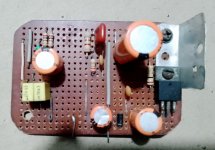
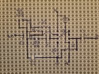
Nice, will post what I came up with when I do. Here is one of my older perfboard builds, STK amp.Ok, here it is. The IC is missing (i hve it somewhere) because i didn't solder it. At the right side you can see a 7812 regulator & it is part of the power supply. Output cap is 2200uf with zobel network. I think i should finish it for fun 🙂
View attachment 1376056
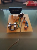
seems interesting, will take a look.Yes, but the vertical output amplifier can make a decent audio amp:
Yet another funny Chip-Amp: The Deviant
Hi there,
I have already described a number of amplifiers based on chips not initially intended for audio, mainly voltage regulators:
http://www.diyaudio.com/forums/chip-amps/176052-now-regulator-chip-jlh-amp.html
http://www.diyaudio.com/forums/chip-amps/192934-se-class-regulator-chip-amp-madness.html
http://www.diyaudio.com/forums/chip...oss-tringlotron-regulator-chip-amplifier.html
http://www.diyaudio.com/forums/chip-amps/193214-class-chip-amp-now-complementary-version.html...
Will do, looks like that this will be my night project tonight, I had to attend a birthday really quick and my 2month-old will wake up soon.Don’t bother with shielded wire, just use a twisted pair to each pot. The tone controls just use them in 2-wire mode. For the volume pot the twisted pair goes to its output (wiper and ground) side. Ok to run single wire to the top of that one, shielding won’t help anyway.
Yes, but the vertical output amplifier can make a decent audio amp:
Sometimes a better one than they used to drive the speaker. The vertical coil took a good 5 watts to drive. And they can’t cheat with PMPO ratings. That would give you a really tiny squashed picture.
Last edited:
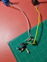
I did a little reading on what causes the opamp to oscillate... I think that I have some other 5532s and TL072 somewhere... will try that just to make sure I didn't get a chinnesse knockoff.
Will also check the rails with oscope...
If this is not it then probably there is too much delay in feedback circutry?
Will also check the rails with oscope...
If this is not it then probably there is too much delay in feedback circutry?
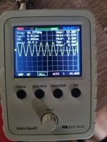
Yes, oscillating. Above audio, 86 KHZ. This is the kind of thing I thought could happen trying to do this with the power stage and why it’s typically a Bad Idea to do with a power stage. The original design Probably relies on the amp running out of loop gain above audio to remain stable. This should work with an op amp that is unity gain compensated. The closed loop gain does shoot for the sky at infinity, but it can be made to limit above audio. Try putting a 100 ohm resistor in the ground leg of the .047 uF cap. That will stop its action above 33kHz. To restore original in band response, the 1k needs to go to 900, but can be left for now. And the easiest way to do that is drop a 10k across it rather than unsolder and try to find a 910 ohm.
Yeah. The 1k/.047uf causes the closed loop response to rise above 3.3 KHZ, and just keep boosting the higher it goes. Until the amplifier itself (that the feedback is around) runs out of gain. The 100k pot and .022 take a variable amount of this boost back out. At some frequency layout will cause isolation issues due to unintended coupling at the very high resulting gain and you get oscillation. Adding a resistor at 1/10 of the value to limit the extra HF boost to 10X should keep the gain from climbing too high. The corner frequency for that is 33KHz so it shouldn’t interfere with what the tone controls were designed to do. The extreme boost that could happen with the bass won’t hurt anything because frequency is too low for stray coupling to cause problems, and the inherent phase shift approaches zero at DC so there is no potential source of oscillation.
Hey it works and it work pretty good. We had essential build "BOSE simulator" hehe.
Highs are more or less average, but lows/mids...
I connected PC, Yamaha A-S500 hifi amp and Dali Concept 1 speaker (8inch woofer)... the bass can be boosted till bookshelf speaker sounds like much bigger woofer.
The sound is spot on, it sounds exactly like the stock radio. I can't find the exact words for the bass, I would say it sounds forced and loose, floaty... I know that this sounds like something noone wants, but that sound is the charm of that radio.
It has a bit much gain, on PC I had to lower volume to 50%. This is not to bad because my tuner actually has a bit lower output. The 2.2k - 4.7k resistor going from first opamp output to second opamp input... I used 3k, if I go higher, gain will be lower right?
It is still oscillating, but now at 223khz, is this stil a concern or can be left as is?
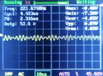
Thank you sir, you had lead me to the right path.
Highs are more or less average, but lows/mids...
I connected PC, Yamaha A-S500 hifi amp and Dali Concept 1 speaker (8inch woofer)... the bass can be boosted till bookshelf speaker sounds like much bigger woofer.
The sound is spot on, it sounds exactly like the stock radio. I can't find the exact words for the bass, I would say it sounds forced and loose, floaty... I know that this sounds like something noone wants, but that sound is the charm of that radio.
It has a bit much gain, on PC I had to lower volume to 50%. This is not to bad because my tuner actually has a bit lower output. The 2.2k - 4.7k resistor going from first opamp output to second opamp input... I used 3k, if I go higher, gain will be lower right?
It is still oscillating, but now at 223khz, is this stil a concern or can be left as is?

Thank you sir, you had lead me to the right path.
With an 8” woofer, there is probably TOO much bass. With the little speaker that was in the radio, in its leaky box, it’s probably about right.
The 220 kHZ can probably be fixed by hanging a hundred or so pF between the + and - inputs of the op amp. It might take better supply bypassing to get rid of too.
Increasing the resistor in question is how to lower the gain, if needed. Thats why I had a range - I figured the right value would be between the two. With the original 220 ohms the gain would be way too high. For a preamp.
Yes, with 8" woofer there is way too much.
I had connected the speaker of the radio and it is very good.
Sorry, my bad, I totaly forgot that my quick power supply will probably have some ripple. I will try with capacitor between inputs if needed, however first I must make a good clean power supply. As it is right now, I expected hum or buzz, but there is none, so this is good.
Noted on the gain, will change resistance if needed when tuner will get connected to it, probably I will end up with 4.7k, if not else I like to protect my projects against unexperienced folks that may try to push the volume & bass too far.
Great progress so far, I will take a look in my "pile" for amplifier IC, I hope that I will find something good because so far tuner & preamp are perfect.
- Home
- Amplifiers
- Solid State
- Amplifier suggestion for old 3w speaker
