I would, but I have no idea on how to come up with the schematic.It’s also another reason to get that stuff out of the feedback and implement “somewhere else”. What’s one more op amp among friends? 10 milliamps of current draw?
If I did do it separately, I’d run it inverting and bump the 220 ohms up till midband gain was between 1X and 4X. Drive it with the other side of a dual, strapped as a follower. Decrease the power stage gain as needed. Result? Better gain structure and lower noise.
crease the power stage gain as needed. Result? Better gain structure and lower noise.
Depends on the 2002/3/4/5. Some are singleton input like that, others differential high Z. I thought they all were singleton CFAs until I was shown otherwise. The originals were, but not necessarily now. In either case 220 ohms usually low enough impedance to work with a singleton input. I use resistors 180-220 in that position all the time. Any doubt? Divide all resistances by 10, multiply caps by 10 and 22 ohms is damn sure low enough. I would probably do that anyway, at least with that IC. It’s just another step which may or may not be needed.
TDA2030 is damn sure differential. No one ever made a singleton version as it was intended for split supply.
TDA2002/2003/2005/2007/2009 all use the same schematic with a single transistor input stage, but not the TDA2006 wich
use a diferential as well as the 2020/2030/2040/2050/2052.
Anyway these were nice chips, particularly the TDA2030/2040, the TDA2003 was good as long as the voltage was kept
under control as it s rated 18V max but it doesnt hold that voltage for long, i ve seen many 2002/2003 of car radios
that failed surely due to short voltage peaks, much less due to abuse as at 14-15V they were very rugged.

I’ve seen schematics for sone of the non-STs that use differentials. I guess it depends on whether they are copying ST or NEC. Functional equivalents, different front end. Those low saturation transistors are absolutely required, regardless. Those don’t have squat for Vceo, so thats why 18V is the max. And if the feedback path impedance is sufficiently low it works on anything, even a differential VFA. Scale the whole network impedance down to where the 220 ohm to ground off the - input is 22 ohm, and you’re golden. Use whatever power chip you like and can get. Just don’t use some junk like LM380 or LM377. Those (and all of their successors) gave IC amps a bad name. Especially run “flat” with a bass roll off at 200 Hz due to a 220 uF output cap!!!
I would, but I have no idea on how to come up with the schematic.
Ain’t hard. Just use a 5532 op amp to drive that miserable 1k load. Alternative is scale all impedances up and be stuck finding a 5 meg pot, or my solution which is yet still another layer of complexity. But I’m stubborn enough to do it (emitter follower and 20 mA current source, inside the feedback. MPSA06’s are cheap and I have more of them than I do 5532’s).
Attachments
Thank you again for everything.
I will build it.
But if I understand correctly it is best not to use TDA2003 if I plan to run it at 18v and I can use whatever power IC with suitable power rating?
The preamp if I think correctly has 2 inverted buffer followed by inverted tone control stage... Inverted + inverted = noninverted output
Also now I have problem with Ic power ratings.... here we have 18Vs rail voltage to get good 3watts, datasheet of TDA2003 states 6watts @4ohm 14.4Vs.
Is this PMPO and we are talking about RMS?
Should I rather find Vpp of Ic in question and use this formula to get the power?
(Vpp * 0.707 / 2)² / 4ohm
Is this PMPO and we are talking about RMS?
Should I rather find Vpp of Ic in question and use this formula to get the power?
(Vpp * 0.707 / 2)² / 4ohm
No, we’re talking about 6 watts at crazy high distortion (heavy clipping). They would call it 25 watts PMPO. You get 3 clean watts with 10V p-p. An 18 volt supply will guarantee you get that even if it sags to 12 under load. If you start out at 14 you might sag to 10 or 11 and not get the power you expect. If your little transformer’s regulation is better you can start with a little less voltage, but it never works that way. People usually underestimate how much oversized the transformer needs to before it can stay stiffly regulated. My experience is that “12 volt transformers”, which give about 18DC at no load after the rectifier work fine and give the desired result. Even with the 2002.
If you have or can get the Toshiba TA7205 I like those better. A lot better. They are best run with the gain flat and would require the tone shaping to be done ahead of it.
If you have or can get the Toshiba TA7205 I like those better. A lot better. They are best run with the gain flat and would require the tone shaping to be done ahead of it.
Ok, understood.
I might have some good genuine ICs from 90s as I have some old car radios in the garage. Will check.
I will see if I will be in store on time, I'm at work now.
If so, I will check what they can offer me.
I might have some good genuine ICs from 90s as I have some old car radios in the garage. Will check.
I will see if I will be in store on time, I'm at work now.
If so, I will check what they can offer me.
We used to have land off-grid and I used to make boomboxes with car speakers and car radios that were driven hard at gatherings. Systems up to 3 radios and 10 speakers... Now I know why every single system sounded "harsh, dirty" when past 70% of volume.
Yes, Here in india it's a common audio ic (TDA2003) in almost all cheap generic CRT telivision boards. Of course for repairing work, CRT is a product of past now.sum makes them alongside cdil
They tended to use other stuff that wasn’t as good in cheap CRT TVs for sale over here. They stayed with ICs in modern TVs (but it did improve with picture quality) - thats where the lion’s share of LM3886’s were going for a while. The other half went into powered near field studio monitors. Until class D for the most part replaced it.
And no one repairs a CRT TV here.
And no one repairs a CRT TV here.
I got to the store, but couldn't get the list of power amp ICs, I could take a picture, but 1/2 drawers are empty and obsolete :/.
I will see what I have at home first.
But I did to manage to get parts for the preamp. I also grabbed 2x 9v 20VA transformer, so I can test the preamp.
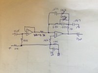
I did draw another schematic, just to make it easier for me to transfer this to perfboard layout.

The circuit is not for split supply right?
That 2x 10k divider got me confused...
I presume that it is for single supply, in that case I must connect 10k (R1 on my schematic) to V+ right?
What would need to be done to get split supply version from this one? I think that I should just remove R1, R2 and connection between R1,R2 and R4 right? Should Input be grounded with resistor anyway? Or 100k towards V- and another 100k towards V+ do make a divider?
I will see what I have at home first.
But I did to manage to get parts for the preamp. I also grabbed 2x 9v 20VA transformer, so I can test the preamp.
I did draw another schematic, just to make it easier for me to transfer this to perfboard layout.
The circuit is not for split supply right?
That 2x 10k divider got me confused...
I presume that it is for single supply, in that case I must connect 10k (R1 on my schematic) to V+ right?
What would need to be done to get split supply version from this one? I think that I should just remove R1, R2 and connection between R1,R2 and R4 right? Should Input be grounded with resistor anyway? Or 100k towards V- and another 100k towards V+ do make a divider?
Last edited:
If you are using a split supply, ditch the bias divider and hang the 100k’s directly to ground. And put a .01 or 0.1 uF ceramic cap directly between pins 4 and 8 of the op amp. That’s a good idea regardless, and then you can get a bit sloppy with the supply wiring and not run into problems.
Ok, will draw, just to double check I don`t get something wrong before building.
0.01 or 0.1uF ceramic cap... can I use something in between those values right?
I also presume that if I will run amp in split supply, from same supply, it is better to run also preamp in split supply to load both rails equaly?
0.01 or 0.1uF ceramic cap... can I use something in between those values right?
I also presume that if I will run amp in split supply, from same supply, it is better to run also preamp in split supply to load both rails equaly?

India has a huge population, probably 1/4 of worlds total population & not everyone wants to throw their old CRTs because of their low scale of earning. But here no one sell CRTs anymore because its obsolete now. I myself using LED monitor while typing the post. EDIT:- Btw for info the price of a brand new CRT circuit board is apporx $15, so why not?but people sure do throw out crt tv's
- Home
- Amplifiers
- Solid State
- Amplifier suggestion for old 3w speaker