If one is inverting and one noninverting, a bridging opamp is not needed. Just tie the inputs tigether. An opamp is still needed if you want balanced ins. If both sides are inverting, then an opamp is needed for to re-invert one. This is probably the best arrangement, as the inverting configuration has a common mode voltage of zero, and a gain-bandwidth advantage over noninverting. The one thing that must remain constant is the the low side must be in the inverting configuration or you get no output from the low side. You can always play with the phase back at the balanced in to put it whichever way you want (ie, make the whole amp non-inverting or inverting).
I have heard of 3773's being faked. Or, rather, very grossly out of spec copies from Chinese makers (not the same as an outright fake marked "ON"). But they are still a standard product and there is still an incredible amount of new old stock and surplus out there - including really good ones from 30 years ago.
Nobody fakes a 2N3055. Most of the time when you do get a fake, it has a 3055 die in it. Unfortunately, the passivation process is horrible (white silicone) on these fakes so they're still not as good as an old Motorola from 1973.
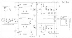
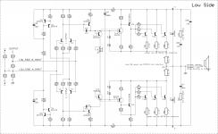
Still trying to figure out the best and easiest way to do the bridging. I changed a few things again on the schematics (attached here). They show the inputs as A and B, to help in the discussion.
I was trying to pick the right thing from the crown amps, which are all or almost all, using the exact same setup, besides the number of output pairs and some small details.
They make intensive use of opamp and comparators for their odep stuff, which complicates things quite a bit.
Trying to cut through all the background noise to isolate the part that we're interested in for bridging, is not so easy. I see they have a totally separate psu of +=15V for most of their opamps and comparators circuitry, using the unregulated +-24V before the 15V regulators for a couple of things, and that separate psu does make use of a center tapped secondary, tied to ground. Plus their pre-driver stages are also powered from that same non floating power. The drivers and outputs are then the only ones powered from those floating rails.
Very complex compared to the standard we're used to.
The hard part, is their input opamps they call "error amp" and then that voltage translator stage.
There is no feedback taken from the low side at all, I guess it simply follows the high side. The part that should be of top importance is that divider network that receive the output as feedback and then a set between the rails. Then there is a tie to ground there, but not in the middle point. Difficult to make out.
I'm wondering, by removing the feedback entirely as I did on the low side, we have the 2 inputs of the diff stage there, which could simply be used in the opposite way as the high side. And their signal levels are compatible, should be the same.
What if we tie the A input from the low side to the B input on the high side, and the B input from the low side to the A input on the high side? this makes them automatically opposites, so inverted as they should be in regards to each other.
Would this work? Leaving the high side as it is, with its feedback.
If we did this, then there is no need for that bridging opamp.
Attachments
If one is inverting and one noninverting, a bridging opamp is not needed. Just tie the inputs tigether.
That's what I was just pondering in my last post. I didn't see this one until now.
An opamp is still needed if you want balanced ins.
And it would allow choosing the phase as well. Doing it as I was just posting, swapping the inputs from one side to the other, automatically makes them opposite. Although I can't make out which one inverts.
I'm thinking by default the original amp does invert, but I can't be sure of that.
The one thing that must remain constant is the the low side must be in the inverting configuration or you get no output from the low side.
If this is how it turns out with my current arrangement, then it's ok, but if it's the high side that inverts and not the low side, if it does need to be the one to invert, then we can just swap the A & B inputs on the high side, so we change the situation on the high side.
The inverting input on the xlr being pin 2, if it turns out the amp does the opposite of that is needed, then we can just swap pins on the xlr and make the balanced opamp do the rest.
You can always play with the phase back at the balanced in to put it whichever way you want (ie, make the whole amp non-inverting or inverting).
That's what I meant in my previous statement.
I have heard of 3773's being faked. Or, rather, very grossly out of spec copies from Chinese makers (not the same as an outright fake marked "ON"). But they are still a standard product and there is still an incredible amount of new old stock and surplus out there - including really good ones from 30 years ago.
I had never heard of the 3773s being faked, but that's good to know. But my old stock should be fine, because those date back to the 70s and early 80s.
Nobody fakes a 2N3055. Most of the time when you do get a fake, it has a 3055 die in it. Unfortunately, the passivation process is horrible (white silicone) on these fakes so they're still not as good as an old Motorola from 1973.
My old stock is also just as old as the 3773s, so I'm not worried about that part. However, this amp will be nice and who knows, I may want to make more than one and I'll need more trannies...
The "error amp" is just equivalent to the differential input stage. Crown uses an op amp front end, as do many PA amplifiers. This is to eliminate the need for matched pairs in production and to provide additional loop gain. The "voltage translator stage" is just a level shifter to drive the VAS.
In the Crown amp, the low side's feedback is taken from the high side output. The low side's output is REALLY the power supply! In the QSC amp, the "speaker out" is taken from between the power supply filter caps. If you are unsure about what to do with the feedback, just use the "N102" resistor network from the MA2400 schematic. The + input of the low side opamp is the "A" input and the - input is the "B". "CH1 FB" goes to the high side output. These resistor values will cause the low side amp to have a noise gain of 10, which will likely be ok stability wise. This may be noisier than you want - you can always build it and see. If you have enough loop gain stability, the closed loop gain of the low side can be reduced (even to unity gain).
As far as your proposed arrangement of just swapping phase and paralleling the inputs - it may work. It also may not. The feedback network in the MA2400 has been proven to work.
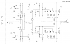
So here it is. I tied the diff stages' inputs in a crossed manner.
I figured out a way to show this on the schematics (see attached).
This removes the feedback network from the low side (R48 & R49 & C32), which saves more space and simplify things a bit.
Now will this work?
One interesting point, is that the low side has nothing referencing to ground at all except for its grounded output.
I guess a good simulation of this setup would say if this works or not. Now this is a bridge...
Attachments

just use the "N102" resistor network from the MA2400 schematic. The + input of the low side opamp is the "A" input and the - input is the "B". "CH1 FB" goes to the high side output. These resistor values will cause the low side amp to have a noise gain of 10, which will likely be ok stability wise.
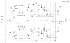
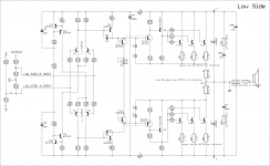
ok then, here are updated sch, with a network arranged the same with the same values. But those set the gain for that side, and I suppose we need to do something on the high side's feedback and gain values to match.
Aren't R5 and R2 determining that closed loop gain on the high side? Does R4 have something to do with it too? And R3 probably doesn't do much for that.
This may be noisier than you want - you can always build it and see. If you have enough loop gain stability, the closed loop gain of the low side can be reduced (even to unity gain).
What else could we do to improve this if that's the case?
If we make the low side unity gain, that can't work with a different gain on the high side. We can't have different gains on each side, or they'll "fight" each other and this would cause problems.
Attachments
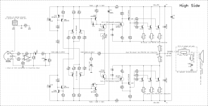
I looked at the high side, which is still basically standard, to figure out if the input (A input) is inverting or not.
I think, unless I'm wrong of course, that the amp in its default config, which this side is, is not inverting. So this means that my reversal of the inputs on the balanced input opamp may be unjustified. Please correct me if I'm wrong.
Now on the low side, having used the A input on that side as the + input, this should be correct.
The main thing to verify is that gain, on both sides.
Connect R93 from low side input to GND.
If R94/R93 = R48/(R19||R92) then the low side becomes effectively unity gain inverting, with respect to the high side output. You're dividing down the supply reference by the same factor as the low side gain. I'm pretty sure R92 needs to be 3.65k (might have been a typo, but this small difference probably wouldn't matter.
In the old school, when you "bridged" an amp, you just turned the 2nd amp into a unity gain inverting. Unity gain amps like to oscillate, so it's best to have some gain.
Connect R93 from low side input to GND.
Only to make calculations right?
If R94/R93 = R48/(R19||R92)
For R19 you meant R49 right?
R19 is in a zobel.
then the low side becomes effectively unity gain inverting, with respect to the high side output. You're dividing down the supply reference by the same factor as the low side gain. I'm pretty sure R92 needs to be 3.65k (might have been a typo, but this small difference probably wouldn't matter.
No typo, because I see that same value on several schematics. I have many, the MT, MA, PT...
On an older MT1000, that one is not even there at all, they have 2 33k and 2 3k3, omitting the 3k56.
In the old school, when you "bridged" an amp, you just turned the 2nd amp into a unity gain inverting. Unity gain amps like to oscillate, so it's best to have some gain.
That may be why they have so many caps here and there.
Opamps also tend to cause more oscillations, from my own experience, so maybe making a 100% discreet one may be less prone.
How are we doing so far?
You had R93 connected incorrectly - go back and look at the Crown schematic.
R49 looks like 19 in my PDF, but you know which one it is.
It does seem odd about the 3k56. It should be 3.66k according to calculations, and 3.65k is a standard 1% value. It's probably not enough to matter. It may be better to have ever so slightly more gain in the low side to make sure it clips first (not leaving any voltage swing on the table).
Opamp input stage amplifiers are more tricky to stabilize, but once you learn how it's easy. They need lead compensation in addition to Cdom, and have minimum gain requirements. Also, opamp based PAs have enough loop gain where you can put in local feedback in various places to make the harmonic structure more 2nd-order-dominant. And don't underestimate the importance of having the input stage matched and Iq balanced if you want better than .1% THD20k. With an op amp front end this has been done for you, even with a cheap Bi-fet. If .2% THD20k is good enough you can get away with throwing just about anything in the input stage.
You had R93 connected incorrectly - go back and look at the Crown schematic.
OOPS!!!
Right again, I screwed that one up.
Updated, attached.
It does seem odd about the 3k56. It should be 3.66k according to calculations, and 3.65k is a standard 1% value. It's probably not enough to matter. It may be better to have ever so slightly more gain in the low side to make sure it clips first (not leaving any voltage swing on the table).
What happens if the gain isn't the same on each side?
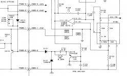
I'm attaching the snippet from the MA2400 sch that shows that divider network.
This is the one I used as a base, and as you can see, they do have 3.56k clearly on there, and I see that value on others... Except for that older MT1000 that has 2 x 3k3 and only 4 res total instead of 5.
Attachments
Here I am again pondering on that opamp power supply issue. Since there is only one transformer and a single secondary, there is no power to get anywhere else.
However, if I take power from the secondary, before rectifying, and use a diode bridge to separately make an other supply for the opamp. We can't prevent the gnd from swinging and there is no center tap to fix that ground. Actually we can't fix it, it must swing in regards to the rails, but not in regards to the little rails made by that extra diode bridge.
If I do this, when the ground swings, will the power coming out from the diode bridge also swing in regards to the ground?
Imbalance in gain means the rail voltage won't divide evenly. Obviously, it's not too serious if it's a bit off (3.3k vs 3.56k in a divider). Even in a cascode it won't be perfect. If you were pushing the transistors to the very edge of SOA in the high dissipation region it might be an issue. The only thing we're pushing with the 3055 is Vceo. The s/b breakpoint is 40V, which is well over half the expected max Vce in the application. This is far more comfort margin than using a typical high fT type with a 30V breakpoint on +/-55V rails.
Here I am again pondering on that opamp power supply issue. Since there is only one transformer and a single secondary, there is no power to get anywhere else.
The opamp supply worked out in post 174 works perfectly. You can't draw much current but you don't need much. The QSC circuit doesn't even use the diodes - and yes, the dropping resistors do bleed off some of the cap charge when the rail falls below 15V. It doesn't hurt anything so long as the circuit it's powering can handle a bit of ripple.
I haven't changed that psu for now. (sch attached)
I only removed that opamp that won't be needed.
I just tried again calculating that dropping resistor, and that can't work, it needs to be at least 5W and the zener over 4watts. Not practical that way. I must be leaving something out.
I don't want to use a single opamp package, because I don't want to add an other trimmer to adjust offset, so what I can do instead of grounding the inputs on that left over opamp in the dual case, is make use of it, as a simple follower behind the balanced input opamp. That way the whole circuit is used for the best and I don't have left overs hanging.
Now when calculating the opamp psu, I was trying with a load current, consumed by the opamp, of 8mA. This time I tried using 5mA. I had found a resistor value of about 66ohms before, and with 5mA I find about 70mA. But more than 5watts, and the worst part is the zener power, which I doubt could be found and it would be too big and energy wasting.
Isn't there an easier way? Or perhaps I'm calculating this wrong.
Attachments

Member
Joined 2009
Paid Member
Why not use a transistor in each rail in the topology of a capacitance multiplier. Then add the zener to the base of the transistor to pin the output voltage to something suited to the opamp.
Love this thread - the 2N3055 may be old, may be rough, but it's a classic and there's more to enjoying an amplifier than aiming for the lowest distortion with the latest silicon.
Love this thread - the 2N3055 may be old, may be rough, but it's a classic and there's more to enjoying an amplifier than aiming for the lowest distortion with the latest silicon.
Why not use a transistor in each rail in the topology of a capacitance multiplier. Then add the zener to the base of the transistor to pin the output voltage to something suited to the opamp.
I'm not familiar with that, could you draw up something or explain in more detail?
This might be good to try.
Love this thread - the 2N3055 may be old, may be rough, but it's a classic and there's more to enjoying an amplifier than aiming for the lowest distortion with the latest silicon.
Abso-freakin'lutely!
Some have been poo-poo-ing us for using such old trannies. Of course they can't compete with the top of the line new ones, but what we're doing should get the best out of them and we're having so much fun in the process.
We'll build that thing and make it work.
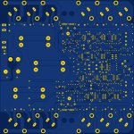
btw: I'm almost done layout with the schematics the way they are now. Although a couple of parts aren't calculated, they're more or less already sized up, but a few of these things can easily be changed in no time, since the bulk of the work is now done. It should look pretty nice. I'll post a preview shortly.
- Home
- Amplifiers
- Solid State
- Amplifier based on 2N3055