I am now considering the addition of the protection circuitry, as a VI limiter if we can get this to work right. I would hate to use a protection that operates on legit signals and within the normal range, so this must not be acting below clipping.
To be able to get the max out of the outputs soa, the VI protection should work better.
And on that note, I was giving some thoughts about the relation between high and low side, since the low always follows the high, then I don't think the low side needs those protection circuits, does it?
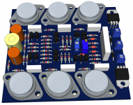
Adding this, no matter how small of an increase in the number of parts, it will require more space, so I'm going to widen the size to 110mm, so the board would be 110x110 instead of 100x110.
To be able to get the max out of the outputs soa, the VI protection should work better.
And on that note, I was giving some thoughts about the relation between high and low side, since the low always follows the high, then I don't think the low side needs those protection circuits, does it?
Adding this, no matter how small of an increase in the number of parts, it will require more space, so I'm going to widen the size to 110mm, so the board would be 110x110 instead of 100x110.
Hi guys!
Here high-quality schematic
cheers!
Here's complete schematic!
Attachments
Last edited:
Here's complete schematic!
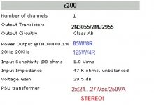
This is another example of a design that exceeds the 3055's Vce0 limits and the rated power is also overstated.
We're working on a design with a 35V rails, which theoretically would also slightly exceed the Vce0 limits. We're "pushing" it, but this one pushes further.
Perhaps the 3055H may be ok, if it's the real one with 100V Vce0.
Here is a VI limiting protection circuitry added to the high side.
No calculations are done yet and that circuit is the standard basic one that is VI and not only I limiting.
There is the question of the R43-D15 and R44-D16 tied to gnd that I'm wondering about. This is a good thing on a standard topo with fixed ground in regards to the rails, but in this case with the ground floating around, is this an issue or not???
I think the use of D13 & D14 is warranted, as they protect T23/24.
The C8/9 caps are just there to prevent action on fast transients.
And finally C6/7 would only be there for stability, for oscillation prevention on those trannies.
Having this quasi topo with only a common resistor from each outputs group going to the speaker output bus is simple (only one sensing resistor needed).
Attachments

Coming back again on that issue of the P1 bias adjusting trimmer.
I ran some calculations, using a resistor in parallel on P1. We can't get the same range of values according to the wiper, but if I understand it right, in the current config that wiper's "normal" adjustment is somewhere around 20%, which means we would never need to go near 100%, so 100 ohms is not necessary.
So, if we put P1 in parallel with a resistor, I found that using 220ohms for P1 on a 33ohms resistor would provide a range of values up to nearly 29ohms, and the wiper would be somewhere below 25% to arrive at a similar value that we had with the 100ohms pot at 20% wiper.
This pot should be a multi-turns, to keep a smooth enough adjustment and only less than a few % of its range would be used.
We do not want to have the total combined value to go too far up, so the bias current can't be too high. The original value of 100ohms is likely too high as it is and it's important to double check that wiper before first power-on to make sure it's at or near 0% to avoid surprises with too high bias.
There is the question of the R43-D15 and R44-D16 tied to gnd that I'm wondering about. This is a good thing on a standard topo with fixed ground in regards to the rails, but in this case with the ground floating around, is this an issue or not???
If the input for the low side is fed from the high side's output, the low side will continue to provide the proper "ground" and split the rail voltage even when the VI limiter is activated. This is why you don't want/need a limiter on the low side. There are also several other VI limiter types that do not need a ground reference (it references the opposite rail). But this one is relatively easy to calculate and it works.
If the input for the low side is fed from the high side's output, the low side will continue to provide the proper "ground" and split the rail voltage even when the VI limiter is activated.
YES! I just now realized this as you explain this. Since the limiter would only activate on output short, then the high side output is then basically at ground level, which does split the rails even around the ground.
Make sense now.
This is why you don't want/need a limiter on the low side. There are also several other VI limiter types that do not need a ground reference (it references the opposite rail). But this one is relatively easy to calculate and it works.
Agreed, not remains proper calculations to be made, in regards to the soas...
btw: is my implementation all correct?
Implementation looks fine. Now we all get to argue about how lax/consevative the SOA protection needs to be....
Implementation looks fine. Now we all get to argue about how lax/consevative the SOA protection needs to be....
Yea!!! Let's start arguin' 😛😛😛
Not being certain I had plotted my load lines right on the soa chart, I can't be certain about how comfortable we are within that soa. But if it's correct, or close to it, then we seem quite comfy there, with room to spare on the 2 ohms load. And if that is the case, then the protection should be set well above the clipping or any "normal" transient operation.
Those protection circuits, although they can be efficient, they also can harm sound if they're set too low.
I grabbed LTSpice (for mac) lately, and tried getting used to it somewhat. Using that can also guide in the calculations, but it's very theoretical and some extra thought must be given beyond sims. I'm far from being able to properly use this tool for now, but I can look at a few things and when I figure out how to rotate a component, maybe I can draw up the updated schematic to include the protection circuitry.
If I can manage to input the whole amp, both sides, plus its proper psu in a single sim, that might be interesting to see the results and find out if it's already viable.
Could I have your postal address please ? Tomorrow (Monday) I am planning
to visit the post office for everybody else interested in the PCB.
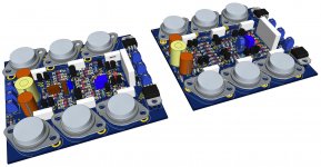
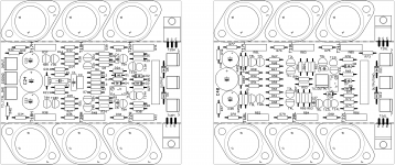
I was wondering if that board would be easily modified for the purpose of making the grounded bridge. Our schematic has been evolving and the main amp has changed quite a bit and the low side even more. We've come fairly far from the original design and I wonder how this board could be adapted to handle this.
Plus it takes 2 boards to make the bridge, and they're not "configured" the same.
What do you think?
Implementation looks fine. Now we all get to argue about how lax/consevative the SOA protection needs to be....
Since the schematic would be basically the same and it's the values that change, then when someone wants to make it act a little differently, then he/she can change the values.
I think when we work out all the details, we can put up a nice and easy to use spreadsheet to calculate those values in a heartbeat.
I am pondering the protection of T5 & T6 (high side) when the output is shorted and the protection is acting.
Although the drivers and outputs have their drive removed, the outputs on the pre-drivers get sent to the output, so they see that short almost directly. Now I'm guessing that with the high side output shorted, to ground, which is the low side's output, the reaction of that low side would be to bring the ground at the middle point, and freeze it there. Am I right or not?
The we would have for example T23 pulling hard on T5's collector towards that output shorted to ground.
Perhaps with the amp's input still driven at the max, let's say to the point to want to make the amp clip. Then T23 would probably win in regards to T5 to bring that driving signal coming from T5's collector down. So, then we would have not far from V+ across T5 as Vce (minus the drop on R23, D17 and T23's Vcesat).
With driving current coming from the input diff stage, trying to saturate T5, and the Vce that would resist coming down, I'm thinking the dissipation in T5 would be too great for it. Doesn't this require some attention? Do we need to add one more trans on each pre-driver to protect them?
You can add additional protection for the VAS if you want. As it is now, you'll get about 22mA through it if you activate the VI limiter into a short. If this is on half the time, it's probably tolerable. With a diff pair input this stage's current is limited by what you get when the diff pair is steered all the way to one side. If your input stage topology can go into class B in normal operation (ie, opamps, CFA's), then you've got to worry about how hard the VAS can be driven in overload.
You can add additional protection for the VAS if you want. As it is now, you'll get about 22mA through it if you activate the VI limiter into a short. If this is on half the time, it's probably tolerable.
If it was on all the time, then we would be at the limits of dissipation, but perhaps half the time is ok then. So we'll just leave it as it is now.
However when this amp is going to be used with 3773s instead of the 3055s and the rails increase, then it might be a good idea to protect those, or perhaps use beefier ones.
"Would you have a higher resolution of that schematic sheet? "
Sorry, no.
That is the only copy of the Hadley that I have come across. I used it as the basis of the complementary design I posted below it. The new one should be clear enough to show how it works. I think Bongiorno worked for Hadley about that time frame, and I know Nelson Pass was aware of it.
Sorry, no.
That is the only copy of the Hadley that I have come across. I used it as the basis of the complementary design I posted below it. The new one should be clear enough to show how it works. I think Bongiorno worked for Hadley about that time frame, and I know Nelson Pass was aware of it.
- Home
- Amplifiers
- Solid State
- Amplifier based on 2N3055