power dissipated in rectifier bridge
I found an another datasheet on that bridge rectifier which takes the ambiguity out, more or less, on how they express the characteristics. That other datasheet does state the thermal resistance as "junction to case", for the same value, so I guess that is what they all mean. Plus that one also provides the forward drop of 1.1V being for the bridge and not per diode.
So I suppose one diode does have a drop of 0.55V and not 1.1V.
Taking the rms current needed for the 2ohms load, we're at 11watts to dissipate in that bridge, so with the 1.5K/W resistance, we have a temperature rise of 17.6 degrees, which would make the bridge a little warm at full power, but not too much to worry about.
Tell me if I'm wrong, but this issue doesn't seem to be something to bother with. A small heatsink can still be slapped on top of that bridge eventually, for the wary of overheating...😀
On the other hand, I was giving some thoughts about how to make the bridging circuitry and I think this might end up being done with an opamp. This requires a separate power supply because we can't make its power from the flying rails.
So to avoid needing an other transformer or one with one other winding or set of windings just for the opamp's power supply, keeping it simple would be to get that power from the same single secondary on the main and unique transformer.
With a simple 4 diode bridge or a small molded one, we can make a separate psu for say +-15 or 18V for the opamp. This will require some more real estate on the pcb, but after the recent changes, the room should be there now. An opamp won't need a big psu after all.
I perused through many schematics from different amp makers using this flying rail topo. It's rather complex and they don't really have easy to read schematics.
Some of them do very interesting things, like for example having all the output transistors' collectors tied to the ground, which is a nice feature, because that's so much easier on the heatsinks being at ground potential, no need for extra insulation.
The only maker to my knowledge using this flying rail to make a grounded bridge is crown. All the others that I've seen do some other funky stuff with flying rails but not bridged.
I'm wondering what else can be needed to get this grounded bridge done right beyond a simple unity gain inverter? For such a job, even a good old 741 would do fine.😕
You don't need to suppose. Just download the datasheet for the diode you are looking at and consult the Vf vs I graph to see the variation of Vf with respect to passing current. To add to your knowledge look at the Vf vs temperature........So I suppose one diode does have a drop of 0.55V and not 1.1V............
Last edited:
On the other hand, I was giving some thoughts about how to make the bridging circuitry and I think this might end up being done with an opamp. This requires a separate power supply because we can't make its power from the flying rails.
Actually, you can. Use a simple shunt regulator using zeners and dropping resistors. Bypass the zeners with 220 uf caps tied to ground. Remember the issue you were wondering about with the small signal rail filters? This is how to use it to your advantage. The caps will store the charge as the rails fly, and keep it clamped at +/-15V.
You don't need separate op amps to do the bridging. To make the grounded bridge work at all, the low side needs to be set up as an inverting amplifier. So just put the low side in inverting mode and use it as an op amp. Normally, its + input is grounded. But in this case that "ground" is really the mid point between the rails. That will force the speaker out and "ground" equally in opposite directions. The divider has a gain of 1/2. You can either run the low side at full gain (inverting) and tie to the source, or unity gain (inverting) and tie its input to the high side output. In either case, an op amp buffer is not a bad idea - and you can use it to make a balanced input.
In the Crown amp, the low side is set up as inverting with 10x gain and fed from the high side output. The mid point divider is further divided down by 10x (wrt ground).
You don't need to suppose. Just download the datasheet for the diode you are looking at and consult the Vf vs I graph to see the variation of Vf with respect to passing current. To add to your knowledge look at the Vf vs temperature.
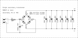
I have, but I just was having trouble with the 1.1V "per bridge" and that "junction to lead" info, so when I compared with a different datasheet, I realize the 1.1V must've been for 2 diodes and not just one.
The graph shows 35A for that bridge up to 50 degrees ambiant, so I did see anything about heatsinking there, and I assume this must also be the case temperature.
Actually, you can. Use a simple shunt regulator using zeners and dropping resistors. Bypass the zeners with 220 uf caps tied to ground. Remember the issue you were wondering about with the small signal rail filters? This is how to use it to your advantage. The caps will store the charge as the rails fly, and keep it clamped at +/-15V.
That sounds simple enough for a power supply, however what happens when the rails are very close to the ground? They can't get too close because of some Vcesat and little details like that, but they can come much closer than 15V.
You don't need separate op amps to do the bridging. To make the grounded bridge work at all, the low side needs to be set up as an inverting amplifier. So just put the low side in inverting mode and use it as an op amp. Normally, its + input is grounded. But in this case that "ground" is really the mid point between the rails. That will force the speaker out and "ground" equally in opposite directions. The divider has a gain of 1/2. You can either run the low side at full gain (inverting) and tie to the source, or unity gain (inverting) and tie its input to the high side output. In either case, an op amp buffer is not a bad idea - and you can use it to make a balanced input.
I like the balanced input idea, since we're having the xlr plug right on the pcb, it can easily be wired for that.
On the low side, then we can more or less swap the use of the diff amps inputs...
In the Crown amp, the low side is set up as inverting with 10x gain and fed from the high side output. The mid point divider is further divided down by 10x (wrt ground).
It might be simple in this one to use unity gain on the low side maybe, and just feed the high side output to it, as long as it inverts.
That sounds simple enough for a power supply, however what happens when the rails are very close to the ground? They can't get too close because of some Vcesat and little details like that, but they can come much closer than 15V.
The rails never stay close to 0 for very long. They move at the audio rate. When it drops below 15V, the cap across the zener will stop charging and supply current to the load (op amp or whatever). When rail voltage returns, the cap will re-charge. With any loading at all, there will always be some ripple but it doesn't really seem to be a problem.
The rails never stay close to 0 for very long. They move at the audio rate. When it drops below 15V, the cap across the zener will stop charging and supply current to the load (op amp or whatever). When rail voltage returns, the cap will re-charge. With any loading at all, there will always be some ripple but it doesn't really seem to be a problem.
I'm just thinking there is a way to help this a little more, to prevent the caps from discharging back into the rest of the amp via the dropping resistor while the rail comes below the zener's level, we can add a diode in series with the dropping resistor, which would keep that charge there with less disturbance from the rails always changing...
How about that?
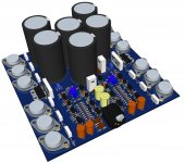
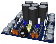
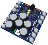
In the mean time, here's some 3D outputs as a preview of the work still in progress. It's not perfect and the layout will change further with the addition of the bridging circuitry. The routing is partial and that too will change greatly.
This is just to get a feel of how it will be.
Attachments

Actually, you can. Use a simple shunt regulator using zeners and dropping resistors. Bypass the zeners with 220 uf caps tied to ground. Remember the issue you were wondering about with the small signal rail filters? This is how to use it to your advantage. The caps will store the charge as the rails fly, and keep it clamped at +/-15V.
Now here is something else that I'm thinking about: where to take that power from? The main rails or those from the small signal front end's?
Take that power from the main rails, especially if you add the bootstrap diodes. You don't want to corrupt the filtered supply for the front end. You will still get ripple even if you take it from the filtered supply - because it is alternately 'disconnected' from and 'connected to' power. Of course, you can RC filter it some more, or use bigger caps than the 100-220 uf in the various QSC designs.
They used a small value cap like that because it was actually part of their protection circuitry. The opamps output had to supply base current for the drivers, and if excessive and long duration, collapsed the opamp supply. For protection of this amp, use a standard VI limiter on the high side amp. The low side will follow the high side so it won't need separate protection.
They used a small value cap like that because it was actually part of their protection circuitry. The opamps output had to supply base current for the drivers, and if excessive and long duration, collapsed the opamp supply. For protection of this amp, use a standard VI limiter on the high side amp. The low side will follow the high side so it won't need separate protection.
Take that power from the main rails, especially if you add the bootstrap diodes. You don't want to corrupt the filtered supply for the front end. You will still get ripple even if you take it from the filtered supply - because it is alternately 'disconnected' from and 'connected to' power.
Ok, sounds good to me.
For protection of this amp, use a standard VI limiter on the high side amp. The low side will follow the high side so it won't need separate protection.
On this protection subject, I raised this issue earlier, because while looking at the SOA situation, I was wondering if having 3 pairs, being under such low rail voltage, would be able to withstand the short and no need any protection circuit. The load to handle is aimed at 2 ohms, because if the bridge is loaded with 4 ohms, that's what we have to handle.
The SOA graphs that I tried putting together were showing that a 2 ohms load (resistive) was quite inside the SOA. I was having issues figuring out how to correctly plot the load line for a reactive load. I may have gotten it right, but maybe not, so that's a point on which I need input.
The SOA plot is at post #74 and it has load lines for 8, 4 and 2 ohms. But that plot only has the resistive load curves.
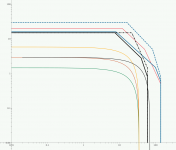
I'm attaching a plot with my attempt at a reactive load line. This may be wrong, most likely.
On that plot, I added for comparison the SOA curves for the 2N3773 and the MJ15003. The 3055's SOA is in black, the 3773 in blue and the MJ in red.
I also added in dotted lines the 100ms curve for the 3773 and the 1ms for the 3055, which I have in the datasheets. There are no curves on those sheets for 10ms.
The load lines are 8ohms in green, 4ohms in red and 2ohms in yellow. That's for one transistor from the 3 pairs of course.
The thin black load line is the one that I'm not sure about. It would exceed the 3055's SOA in Vce, but that's 100% reactive, which doesn't really happen that bad. Can anyone double check my data and correct me if I'm wrong?
In case of a full short on the output, we have full rails on the transistors, the rails would sag the most, maybe even below 30V, and the current would go quite high, but a fuse could blow maybe before the heat becomes an issue. That reminds me that I haven't inserted any fuses on the pcb, but I think there should be only one and it can be on the secondary before the rectifier bridge. It would probably not be wise to have 2 fuses, one on each rail on such a setup...
Attachments
I was reading again some manuals from crown on their grounded bridge amps, and there is one aspect of the grounded bridge that I had forgotten but that may be of importance.
If I get this right, then the output transistors won't even come close to their Vce0 limits. I was reading this time the MA-3600VZ manual, and the interesting part is when they compare the grounded bridge with traditional push pull without the floating ground, they say the in any case, the output transistors will never see more than half of the rail to rail voltage.
So, we're designing for +-35V, and I'm thinking we're pushing it a little too far above the 60V Vce0 limits, which are exceeded by many when they make 3055 amps by the way, and we may actually have the situation where the 3055s will never see any more than 35V anyway.
So if this works that way, then we can even push the rails further and get more power out of that thing.
This will be very interesting to verify in simulations, if someone wants to get into it.
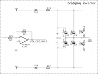
And one more thing about the opamps for the bridging inverter. I'm going to make use of a dual opamp, since they come in the same size package anyway, and use one for bridging and the other for the xlr input balance receiver.
I have the TL082 in the eagle library, so I'll use that one, which should be nice enough for this amp, but I will likely use the SFC2458 or MC1458 on the amp I make, because I have a bunch of those in stock and no TL082 for now. There are surely newer and better opamps of course, but hey, we're making a 3055 amp. Those dual opamps all have the same pinouts, so this is not a problem when time comes to stuff the board.
I have the TL082 in the eagle library, so I'll use that one, which should be nice enough for this amp, but I will likely use the SFC2458 or MC1458 on the amp I make, because I have a bunch of those in stock and no TL082 for now. There are surely newer and better opamps of course, but hey, we're making a 3055 amp. Those dual opamps all have the same pinouts, so this is not a problem when time comes to stuff the board.
So, we're designing for +-35V, and I'm thinking we're pushing it a little too far above the 60V Vce0 limits, which are exceeded by many when they make 3055 amps by the way, and we may actually have the situation where the 3055s will never see any more than 35V anyway.
They were looking at worst case dissipation, not full on or full off. You can still see the full VCE across the off state transistor. But you do get a full +/-VCC swing off the single VCC supply. Run it at 60V, and get about +/-55V of signal.
The cool thing about a grounded bridge amp is that you can bridge two of them and really get stupid power. Of course you need isolated supplies for each, but you need that anyway. Connect ground to ground, invert the inputs (swap pins 2 and 3 on the XLR balanced in on one side) and connect speaker between the two hots. For this you might want to use TIP35's to get the high hFE at high current. They're cheap and available anywhere, too.
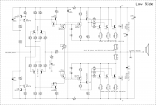
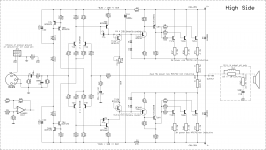
Here are the latest schematics.
Using a dual opamp, with one opamp to make a balanced input on the xlr, and the other should suffice for the bridging inverter.
I am wondering about the balanced input config that I made, because I wanted unity gain and this setup must be inverting, and we can't make a unity gain if non inverting.
The bridging inverter should work fine this way.
I think perhaps if using that balanced input opamp, that we can dispense of using R1, and maybe even simplify a bit this input filter, while making C1 much bigger.
One other thing is we can't use the output directly from the high side to plug into the unity gain inverter. First the input sensitivity of the low side won't match, but we will also overload the opamp's input in the process.
So we can't use the output as is and perhaps we can use that signal from the other side of the input diff amp, after the feedback has come from the output. That input signal is at the same level as the main input.
And lastly, I am having trouble figuring out how to properly calculate that dropping resistor for the zener, since the rail will swing like crazy, all the way to far below the zener voltage, so although I inserted a diode to prevent the caps from discharging back into the main rails, there is an issue with that dropping resistor, which must be able to dissipate a lot and the zener would also need to be of higher power to handle this. Maybe I'm going about it the wrong way, so I need someone to clear this up for me.
Attachments
They were looking at worst case dissipation, not full on or full off. You can still see the full VCE across the off state transistor. But you do get a full +/-VCC swing off the single VCC supply. Run it at 60V, and get about +/-55V of signal.
I think I was reading it wrong. But in any case, the grounded bridge has quite a few advantages, although it's more complicated.
The cool thing about a grounded bridge amp is that you can bridge two of them and really get stupid power. Of course you need isolated supplies for each, but you need that anyway. Connect ground to ground, invert the inputs (swap pins 2 and 3 on the XLR balanced in on one side) and connect speaker between the two hots. For this you might want to use TIP35's to get the high hFE at high current. They're cheap and available anywhere, too.
Sure, the crown amps are stereo, bridgeable and each half of the stereo amp is itself a grounded bridge, so that's quite a setup to get a load more power out of less.
This design can be easily used with better devices. Although we're making this with 3055s, one can get more power by just switching to 3773s, and then other much newer devices could be used, raise the rails much higher and get a huge bang for the buck!
Yes, the dropping resistor will need to handle a bunch of power. You'll probably want 5 or 10 watters. As drawn, your low side amp cannot amplify. It needs to be an inverting (not noninverting) configuration or it simply doesn't work. Note the loop around your feedback - there is no voltage source. If you use a separate bridging adapter, make both amps inverting. Tie the high side + input to GND, the low side to a voltage divider from the rails. Or make the high side noninverting and the low side inverting.
This design can be easily used with better devices. Although we're making this with 3055s, one can get more power by just switching to 3773s, and then other much newer devices could be used, raise the rails much higher and get a huge bang for the buck!
The idea is to make it with CHEAP transistors that you don't have to have a credit card to order and won't get burned by fakes anywhere in the world. Otherwise, we would just use MJ21195s from Newark for everything and be done with it.
Yes, the dropping resistor will need to handle a bunch of power. You'll probably want 5 or 10 watters.
And I'm not sure how to properly calculate it, I found a resistor value down to about 66ohms, and a bunch of power, plus the zener would need to be very beefy too.
As drawn, your low side amp cannot amplify. It needs to be an inverting (not noninverting) configuration or it simply doesn't work. Note the loop around your feedback - there is no voltage source.
WOW!! I didn't even realize this.
You're quite right, I need to rework that aspect.
If you use a separate bridging adapter, make both amps inverting. Tie the high side + input to GND, the low side to a voltage divider from the rails. Or make the high side noninverting and the low side inverting.
I think the best way would be to make the high side inverting, because I think that balanced input opamp, with unity gain, is inverting, and that would re-establish it. Then we need to make the low side non inverting.
The thing, is I'm not certain which is which at the moment. I'm assuming the regular setup is non inverting, so the high side must be that way now, isn't it?
The idea is to make it with CHEAP transistors that you don't have to have a credit card to order and won't get burned by fakes anywhere in the world. Otherwise, we would just use MJ21195s from Newark for everything and be done with it.
Exactly!!! And if we want more power than the 3055s can handle, let's use the 3773s.
Plus it's a lot of fun trying to squeeze as much as we can from those old trannies.
I think we can get so much out of them and get a decent quality in the process.
I never heard of the 3055s or 3773s being faked.
I have several dozens of 3055s around, and over 50 3773s, so I can make a few amps and have spares...
Now that I think of it, the default amp setup must be inverting, because the output signal comes back to one side of the diff amp and the input coming in on the other must be the opposite, so it's a matter of point of view, but as I see it, the signal on the amp's output is inverted compared to its input.
So that means that low side needs changing so it won't invert. But then what to make of the bridging opamp? a follower?
So that means that low side needs changing so it won't invert. But then what to make of the bridging opamp? a follower?
- Home
- Amplifiers
- Solid State
- Amplifier based on 2N3055