The PCB was designed to fit neatly in the smaller HiFi2000 Galaxy chassis’
However because use they come in various sizes, it would be nice to know which size this was as it clearly works...
However because use they come in various sizes, it would be nice to know which size this was as it clearly works...
Last edited:
it's this from HiFi2000 http://https://modushop.biz/site/index.php?route=product/product&product_id=527&search=1GX283N&description=true with the 3mm front panel. I preferred a bit of space at the rear to mount different RCA sockets primarily so that I wouldn't have to be precise lining up the board mounted RCAs.
They are good value cases especially if in Europe.
They are good value cases especially if in Europe.
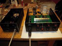
This is very good advice. I built my case snug front AND back, and not only is it difficult to align precisely, but since the connectors align flush with the PCB, you need to drill in excess of 1/2” to allow for RCA plugs of various diameters.… I preferred a bit of space at the rear to mount different RCA sockets primarily so that I wouldn't have to be precise lining up the board mounted RCAs…
I am very happy with how my case is turning out (hopefully pictures soon), but that decision I regret. I wanted to reuse the included connectors, but those going for external cases would be best served by your advice, in my “after-math” opinion.
Rafa.
Nelson and I coordinated the board size to fit full width in the 230x230 chassis but extra room front to back. It better not to use the soldered on rear panel components and there’s room for rear panel mounted components. The kit connectors had to be based on the “open air PCB” build or a chassis build so a choice was made for the PCB mounted connectors. They are a lot cheaper than the panel mount ones so you aren’t paying much more to hav them included in the kit.
The pot can have wires attached by just making a wrap or 2 around each pin, then soldering them..
The 4mm front panel is best for mounting the pot easily.
The pot can have wires attached by just making a wrap or 2 around each pin, then soldering them..
The 4mm front panel is best for mounting the pot easily.
Last edited:
If you keep the pot on the board and use that as your datum in the centre of the front panel its easy to measure the offset of the headphone jack and selector switch and drill appropriate holes - there is plenty of wiggle room for the pot and jack due to their washer and nut fitting. the only precision needs to be with the selector switch. A few washers under the board stand offs gets the height spot on and slightly oversized case floor holes for the stand offs allows side to side wiggle.The pot can have wires attached by just making a wrap or 2 around each pin, then soldering them..
White isolators
OK, a question about the kit.
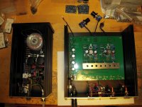
It's time to mount the mosfets. There are 4 white plastic isolators that seem to be the right size for the mosfet screws but nothing in the build photos to suggest where they get installed.
I'd guess it should go on top of the mosfet mounting hole before installing the nut that holds it in place. Can anyone confirm or deny that rumor?
Many thanks.
OK, a question about the kit.
It's time to mount the mosfets. There are 4 white plastic isolators that seem to be the right size for the mosfet screws but nothing in the build photos to suggest where they get installed.
I'd guess it should go on top of the mosfet mounting hole before installing the nut that holds it in place. Can anyone confirm or deny that rumor?
Many thanks.
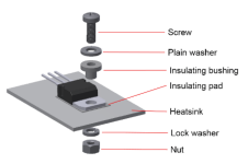
Perhaps could they be what this diagram calls "Insulating bushing" ?? I screen grabbed it from a ST Microelectronics Technical Note, document TN-1225.
Also see the photos next to "Step 5" and "Step 22" in the ACP+ Build Guide.
_
Also see the photos next to "Step 5" and "Step 22" in the ACP+ Build Guide.
_
Attachments
Last edited:
4 largest bolts and nuts plus your white plastic mount the board to the ground plane board. You want the smaller screw and nut set for the mosfets.There are 4 white plastic isolators that seem to be the right size for the mosfet screws but nothing in the build photos to suggest where they get installed.
Perhaps could they be what this diagram calls "Insulating bushing" ?? I screen grabbed it from a ST Microelectronics Technical Note, document TN-1225.
Also see the photos next to "Step 5" and "Step 22" in the ACP+ Build Guide.
_
Thanks Mark. Insulating bushing it is!
4 largest bolts and nuts plus your white plastic mount the board to the ground plane board. You want the smaller screw and nut set for the mosfets.
Thanks captain pugwash. I'd gotten the different screw and nut sizes sorted and the big screws wouldn't even fit the isolating bushing. So they had to be for the mosfets.
Fun build so far.
Well, my ACP+ is up and running! Thanks so much Papa Nelson, Jim, Tom and all the community for your help, the myriad of posts in this thread with recommendations and pointers.
After the minor hiccup with the PSU, I ended up purchasing what was available locally: a fake Samsung 24V laptop-type PSU. It's working, I could bet a month's salary that it is noisy as hell. No way to test it, I will wait a bit to finalize the process of replacing the PSU with the suggested one.
Other than that minor issue, the store's Kit is beautifully put together. Thanks Tom!
The PCB layout from Papa Nelson is so gorgeous, that the "naked" PCB was very tempting! Alas, a cat, a dog and the chance of smaller nieces and nephews visiting (hasn't happened since the pandemic, but one could only hope it is almost over!), prevented me going that route.
So, with some 3D modeling and the help of the community, I decided to go with a hand-made aluminum chassis with a look-through window on top. Since I was going to pair it with a Chord Qutest, it also had somewhat of a "theme" going on:


It pairs lovely with the VFET amp, as so many have already reported:

Since I was already doing the window, I thought that adding internal illumination to the chassis could work nicely, and for late night listening sessions it is actually lovely, it's like a "blue flame" that shines through the darkness during night listening. I am really happy with how that turned out:


Since this could be a little disruptive when watching movies, for example, I actually removed R22, soldered a bridge there, and created the following from the LED position:

This actually allows me to switch the internal LEDs on and off, but keep the front LED on when the unit is on always. Obviously, the left-hand-side R could be a single 2K, but I had none with me, so I went with that. As for the change in general, I don't know the impact it can have sonically (if at all), as 3 blue LEDs that are supposed to be "noisy" could be detrimental, but visually it looks great! 🙂
Since that is probably the more "novelty" part of my build, here's a small collage of the process:

As mentioned elsewhere, I made the mistake of keeping the PCB perfectly snug front to back and using the included PCB back connectors. If you are thinking about this to save yourself some work or the price of 6 RCA connectors, don't. It actually makes isolating the chassis ground and the RCAs ground a nightmare, you don't have an anchor point to grab the connectors while pushing the connectors, so you are putting pressure on them with each push of the cable. It's not a good idea, do NOT follow my example here. It is my biggest regret of this build. I should actually just replace that back plate and redo it with off PCB connectors.
Sound-wise, it really is a marvel! We did some quick A/B/C comparison between our options for the living room system (main system) and the ACP+ won due to it's musicality, it's subtleness and it's fines. Other options where perhaps a little "punchier", but also presented a slightly "harsher" sound, specially for vocals. For large orchestral works, the more punchier options could perhaps be a better fit (at least their synergy with the system, I cannot weight the merits of the ACP+ isolated from what I have with me), but this marvel of a PRE/HPA is really hard to beat! It's staying on our main system for the foreseeable future.
Also, I think it drives my 300 ohm HD600s very well. Perhaps a little less "control" than the WHAMMY, but I could perfectly hear to it for hours on the headphones, so I am not tempted right now to change resistors to match the output impedance, I'm leaving it a 32Ohms for a while and see what comes of it.
Sorry for the long post, embarking on such projects is such a joy that it's just exciting to share the experience with those that have already gone through it and know the nuances, as well as with those that are facing a new build and want some more feedback from the community.
Thanks again to all, but foremost to Papa Nelson, you are the music in our lives and we are eternally grateful.
Best regards,
Rafa.
After the minor hiccup with the PSU, I ended up purchasing what was available locally: a fake Samsung 24V laptop-type PSU. It's working, I could bet a month's salary that it is noisy as hell. No way to test it, I will wait a bit to finalize the process of replacing the PSU with the suggested one.
Other than that minor issue, the store's Kit is beautifully put together. Thanks Tom!
The PCB layout from Papa Nelson is so gorgeous, that the "naked" PCB was very tempting! Alas, a cat, a dog and the chance of smaller nieces and nephews visiting (hasn't happened since the pandemic, but one could only hope it is almost over!), prevented me going that route.
So, with some 3D modeling and the help of the community, I decided to go with a hand-made aluminum chassis with a look-through window on top. Since I was going to pair it with a Chord Qutest, it also had somewhat of a "theme" going on:
It pairs lovely with the VFET amp, as so many have already reported:
Since I was already doing the window, I thought that adding internal illumination to the chassis could work nicely, and for late night listening sessions it is actually lovely, it's like a "blue flame" that shines through the darkness during night listening. I am really happy with how that turned out:
Since this could be a little disruptive when watching movies, for example, I actually removed R22, soldered a bridge there, and created the following from the LED position:
This actually allows me to switch the internal LEDs on and off, but keep the front LED on when the unit is on always. Obviously, the left-hand-side R could be a single 2K, but I had none with me, so I went with that. As for the change in general, I don't know the impact it can have sonically (if at all), as 3 blue LEDs that are supposed to be "noisy" could be detrimental, but visually it looks great! 🙂
Since that is probably the more "novelty" part of my build, here's a small collage of the process:
As mentioned elsewhere, I made the mistake of keeping the PCB perfectly snug front to back and using the included PCB back connectors. If you are thinking about this to save yourself some work or the price of 6 RCA connectors, don't. It actually makes isolating the chassis ground and the RCAs ground a nightmare, you don't have an anchor point to grab the connectors while pushing the connectors, so you are putting pressure on them with each push of the cable. It's not a good idea, do NOT follow my example here. It is my biggest regret of this build. I should actually just replace that back plate and redo it with off PCB connectors.
Sound-wise, it really is a marvel! We did some quick A/B/C comparison between our options for the living room system (main system) and the ACP+ won due to it's musicality, it's subtleness and it's fines. Other options where perhaps a little "punchier", but also presented a slightly "harsher" sound, specially for vocals. For large orchestral works, the more punchier options could perhaps be a better fit (at least their synergy with the system, I cannot weight the merits of the ACP+ isolated from what I have with me), but this marvel of a PRE/HPA is really hard to beat! It's staying on our main system for the foreseeable future.
Also, I think it drives my 300 ohm HD600s very well. Perhaps a little less "control" than the WHAMMY, but I could perfectly hear to it for hours on the headphones, so I am not tempted right now to change resistors to match the output impedance, I'm leaving it a 32Ohms for a while and see what comes of it.
Sorry for the long post, embarking on such projects is such a joy that it's just exciting to share the experience with those that have already gone through it and know the nuances, as well as with those that are facing a new build and want some more feedback from the community.
Thanks again to all, but foremost to Papa Nelson, you are the music in our lives and we are eternally grateful.
Best regards,
Rafa.


Wow Rafa, such a beautiful presentation. And a lovely space too. Congratulations on such beautiful builds.


......... as 3 blue LEDs that are supposed to be "noisy" could be detrimental....
isn't that Fugly!

3 Blue LEDs - no worry about noise - all you got is triple amount of secret Papa's ingredient
isn't that Fugly!
3 Blue LEDs - no worry about noise - all you got is triple amount of secret Papa's ingredient
With 4 GREEN LEDs you gain 45mg of ZM amount

Last edited:
- Home
- Amplifiers
- Pass Labs
- Amp Camp Pre+Headphone Amp - ACP+