Would anyone be so kind to match me up some J113s and tell me their respectful resistor values please? I am UK based and will pay you. I have had a lot to deal with just lately and would like to make building the ACP+ a little more straightforward to take my mind off things. I would really appreciate it guys. Thank you. 🙂
Hi, Gareth! I have the parts, but will not be matching until later this summer/early fall. If you haven’t gotten parts until then, I’ll jig up a pair for you and send it 🙂
Hi, Happy to share if you can wait a bit. Sorry, summer activities take precedence. . .Would anyone be so kind to match me up some J113s and tell me their respectful resistor values please? I am UK based and will pay you. I have had a lot to deal with just lately and would like to make building the ACP+ a little more straightforward to take my mind off things. I would really appreciate it guys. Thank you. 🙂
Good afternoon friends!
I have a small group of questions regarding power to the ACP+, which I wasn't able to find searching the thread. It's remarkable how many searches are comprised of such few letters that it makes hard to search (even using the google search trick instead of the thread search tools).
So here they go:
So, I was looking at playing around with a linear PSU for the ACP+. I know it's not needed, I am not the sort of person that starts hearing subjective improvements, so this is a purely "electronical" challenge, not an attempt to transform this into "that" discussion.
With those previous remarks, I have some questions about the ACP+ and the Salas uBiB. As I understand it (and this is probably very limited understanding!), the Salas uBiB has a Constant Current section which requires you to decide upon the current you will provide to your design. It can't deliver more, but any excess you configure it for would still be demanded from the transformer and dissipated into heat! So it's not like you can say: what the hell, I'll configure it for 10A and hope the house fuse doesn't blow up! 😛
So, I need to configure the current the ACP+ will demand from the PSU, plus an extra 50 to 150mA for the PSU itself.
Does anyone know what that number is for the ACP+? It is, presumably, less than 500mA, as that is the max current of the proposed wall wart, but that is still high enough as to not just eye ball it to that value.
If not, and since I already have a working unit, is it enough to just hook the multimeter between the current PSU and the input jack terminal on the PCB and measure current? My multimeter has two 'red' terminals, one rated at 10A, the other (the usual one) has a 600mA MAX rating (it's a very cheap Chinese "generic" multimeter). Am I safe using the 600mA terminal or should I use the 10A one (I assume there are downsides to using the 10A one, and that is why you have two terminals, or else I don't understand why just not rate the entire thing at 10A!)?
Do you think there are any other problems I may face? For example, if I go with a regulated linear PSU, are the input CRC filter not going to be a problem with linear PSU behind it? Anything else I should look out for?
Thanks in advanced, and, as usual, sorry if this is very obvious to most of you. Thanks!
Rafa.
I have a small group of questions regarding power to the ACP+, which I wasn't able to find searching the thread. It's remarkable how many searches are comprised of such few letters that it makes hard to search (even using the google search trick instead of the thread search tools).
So here they go:
- I received the kits part with the sub-optimal PSU, so I bought a computer-type brick which was supposed to be Samsung, later research (after purchase) shows that the PN I have is for a 14V PSU, so it's a fake brick that actually does deliver 24V. It could be VERY noisy, no idea on the quality of supply (cannot test it either 🙁 )
- I since purchased (with store credit, thanks Elena and Jason!) the correct Triad PSU, hasn't yet arrived
- I am ALSO building a WLS 2018, so I had to purchase a separate PSU
- Since shipping here is really hard, I couldn't make up my mind and went with two choices for that, a Salas uBiB and a VRDN PSU (with big thanks to jimk04!)
- the Salas PCB has an 'extra' V+ tear-off section
So, I was looking at playing around with a linear PSU for the ACP+. I know it's not needed, I am not the sort of person that starts hearing subjective improvements, so this is a purely "electronical" challenge, not an attempt to transform this into "that" discussion.
With those previous remarks, I have some questions about the ACP+ and the Salas uBiB. As I understand it (and this is probably very limited understanding!), the Salas uBiB has a Constant Current section which requires you to decide upon the current you will provide to your design. It can't deliver more, but any excess you configure it for would still be demanded from the transformer and dissipated into heat! So it's not like you can say: what the hell, I'll configure it for 10A and hope the house fuse doesn't blow up! 😛
So, I need to configure the current the ACP+ will demand from the PSU, plus an extra 50 to 150mA for the PSU itself.
Does anyone know what that number is for the ACP+? It is, presumably, less than 500mA, as that is the max current of the proposed wall wart, but that is still high enough as to not just eye ball it to that value.
If not, and since I already have a working unit, is it enough to just hook the multimeter between the current PSU and the input jack terminal on the PCB and measure current? My multimeter has two 'red' terminals, one rated at 10A, the other (the usual one) has a 600mA MAX rating (it's a very cheap Chinese "generic" multimeter). Am I safe using the 600mA terminal or should I use the 10A one (I assume there are downsides to using the 10A one, and that is why you have two terminals, or else I don't understand why just not rate the entire thing at 10A!)?
Do you think there are any other problems I may face? For example, if I go with a regulated linear PSU, are the input CRC filter not going to be a problem with linear PSU behind it? Anything else I should look out for?
Thanks in advanced, and, as usual, sorry if this is very obvious to most of you. Thanks!
Rafa.
Last edited:
Rafa, just simple calc, pic is originally in post #37
roughly 150mA+10mA=160mA ......... simple as that
how to decide which xformer/DC source for regs you did mention, ask in dedicated threads ....... two most important factors are - what programmed current needs to be, and what min. voltage difference (reg in/reg out) needs to be
roughly 150mA+10mA=160mA ......... simple as that
how to decide which xformer/DC source for regs you did mention, ask in dedicated threads ....... two most important factors are - what programmed current needs to be, and what min. voltage difference (reg in/reg out) needs to be
Last edited:
An easy way to measure the current demand is to measure the voltage drop across R18 or R19 and then apply Ohm's Law.
Both resistors are 1 Ohm.
Ohm's Law is V=IR, therefore I=V/R
By the way, if you read this:https://www.firstwatt.com/pdf/art_acp.pdf
you will also find the information.
Both resistors are 1 Ohm.
Ohm's Law is V=IR, therefore I=V/R
By the way, if you read this:https://www.firstwatt.com/pdf/art_acp.pdf
you will also find the information.
Thanks ZenMod and Ben Mah! Really useful information. What may be obvious to your eyes is hidden from mine. I compare it to reading a music score: I can see melodies and rhythms, most people just see dots.
Here, you see currents and flows, I still (hopefully not for always!) see electronic components and understand little else! Thanks for the explanation and pointing out the obvious. I have read this schematic many dozens of times, but failed to see the 150mA on the ground line.
Adding the 100mA ~ 150mA for the PSU, that should be clear enough.
I will confirm with the reading of the drop between R18... still, not sure if that value is the full current or if it should that be tripled since there are 3 such resistors for each channel in the filter?
Also, I must apologize for not "finding" the info on the original PDF (which I have read also many many times!) because I am unsure if those 7W that are reported should be calculated against the 24V from the already-DC voltage or to the 110V from the wall. That lack of knowledge gives me a range from 60mA to 290mA, which, also, is a bit different than the 160mA value proposed by ZM. I take it 160mA is per channel, right? That gives a closer number.
So, I'll learn more and read more and report my findings if they are useful to others.
This saves me a lot of trouble in terms of placing the multimeter in-between the current.
Thanks so much, best regards,
Rafa.
Rafa - current consumption is 160mA per channel
that's all you need to know about this circuit, to ask further questions about (these two things I did mention) setting regs
to increase level of your understanding of circuit: page 2 of article - R18 and R19 are common for both channels ; what you measure across one, you'll measure across other one - they're in series, so same current path
divide voltage reading with 1R and you're getting A

Thanks mighty ZM! Helps a lot, I get it now.

I do apologize.
Thanks for your patience,
Rafa.
I’ll just crawl into a hole and never stick my head out again.Rafa, also page 9 has information on current and measurement.
I do apologize.
Thanks for your patience,
Rafa.
......
I’ll just crawl into a hole and never stick my head out again.
........
don't fret, I'm doing that twice a day


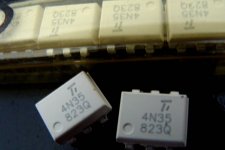
Could anyone say what brand this is, inscribed in this 4N35? Can I use this on my pcb?
Would anyone be so kind to match me up some J113s and tell me their respectful resistor values please? I am UK based and will pay you. I have had a lot to deal with just lately and would like to make building the ACP+ a little more straightforward to take my mind off things. I would really appreciate it guys. Thank you. 🙂
Good video here that explains the whole process of how/why a JFET is used for the CSS and how the resistor can be calculated to pair with the J113 (or other J11x for that matter). Its pretty simple once you understand what is going on.
"That Sinking Feeling" - JFET Constant Current Sources explored... - YouTube
--Tom
Voltage drop is, as expected, a perfectly steady .340V (339.6 according to my DMM)... so 340mA.An easy way to measure the current demand is to measure the voltage drop across R18...
I did add a couple of LEDs that draw extra 10mA on the case (the blue "nuclear reactor" as it was described), so ZM "predictions", Ben Mah's values and Papa's reported values are spot on, as was expected.
This is not a "confirmation", there was none needed given the source of the info and those advising, just to say I did take the time to measure just to not only rely on others and try to learn a little.
I'll start planning the PSU accordingly. Thanks once more!
Rafa.
Last edited:
Soooorry,my mistake!Q3 pins (=j113) on PCB is wrong.
Now when I use J113 on my other PCB project , I found pins is rong!!!
I am SOOOO SOOOOOOOOORRY!!!
I had maked it up now!
The software is AD20 , u can modified it freely.
BRG!

View attachment PASS ACP+ V1.zip
Now when I use J113 on my other PCB project , I found pins is rong!!!
I am SOOOO SOOOOOOOOORRY!!!
I had maked it up now!
The software is AD20 , u can modified it freely.
BRG!
View attachment PASS ACP+ V1.zip
I have doubts. There are cases in which the use of capacitors with higher voltages is not advisable, as they fail to work properly when they greatly exceed the indicated voltage value. In this case, I fear that increasing the voltage too much will harm the ESR.
Good video here that explains the whole process of how/why a JFET is used for the CSS and how the resistor can be calculated to pair with the J113 (or other J11x for that matter). Its pretty simple once you understand what is going on.
"That Sinking Feeling" - JFET Constant Current Sources explored... - YouTube
--Tom
Why was my question quoted?
Is there a build guide for this thing? If so, someone should add a link to the DIY Audio Store page.
Is there a build guide for this thing? If so, someone should add a link to the DIY Audio Store page.
I found it under 6l6's signature. Follow the link for more guides and that page will have the ACP build guide. Here's the direct link:
ACP+ Headphone Amp / Linestage - diyAudio Guides
It's not quite finished but it's mostly excellent. If you've ever put together anything else the guide will walk you through the ACP build pretty painlessly.
Last edited:
- Home
- Amplifiers
- Pass Labs
- Amp Camp Pre+Headphone Amp - ACP+