I have some items coming later this week, soldering Flux, wick and a couple extra Q4's should I need them. Will get back to the project in a few days.
How to check signal output on my pre amp with my DMM? Hard to admit I have no clue about the nature of line level signals.
^ With difficulty I suspect as that kind of thing is really oscilloscope territory.
If your DVM can resolve low AC voltages i.e. it can show for example 320 millivolts AC and not just show a 0 or a 1 for such a low value then you might be in with a chance. You must use a sine wave test tone and should use a lowish frequency like 400Hz which any meter should be capable of showing.
The ACA is very 'insensitive' meaning it has low voltage gain. It needs around 2v rms at the input to reach maximum output.

Are you sure the preamp actually works? How is it attached to everything?
Do you have an rca cable that you can connect to your phone?
Do you have an rca cable that you can connect to your phone?
Continuity - I now have it from both inside rca conductors to their respective r11's ( had to re solder the right channel positive pin ) But I am having trouble getting it from from the common conductor on the left channel rca barrels to the bus wire. I think these were my issues. Still have to get the left channel input to ground. More checking underway. I did order some electronic Flux and some larger tips for my iron. I am learning which is a valuable byproduct of diy audio. Success is near. I was stymied by newbie mistakes, nothing at all wrong with the kit or build guides of course.
I have continuity from the left rca ground to the board but not to the left speaker out. Seems to get lost in the board somewhere. Maybe a bad solder joint?......
Unsure how to procceed.
Unsure how to procceed.
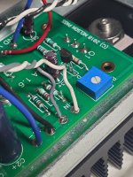
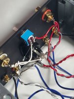
In this photo, you have the left and right inputs cross-wired to the opposite PCBs,
And the left RCA input pin is attached to ground input on PCB, and the barrel to input.
Has this been sorted out? (The photo is a few days old…)
Not sure what you are asking about continuity, something getting lost in the board?
And the left RCA input pin is attached to ground input on PCB, and the barrel to input.
Has this been sorted out? (The photo is a few days old…)
Not sure what you are asking about continuity, something getting lost in the board?
Attachments
I am following the ground from the rca to the board. Near were it enters are the speaker outs. On the channel that seems good I get continuity on the positive speaker out. But not on the one I am having difficulty with. So I am losing the ground signal in the pcb before the positive speaker out. remember I had crossed the input leads to the boards so left and right are not correct. The problem is on input A's ground signal though it goes to the wrong board.
6L6 not only did I have the rca input wiring to opposing boards I had the positive and ground switched on the left input at the board ( I also had a cold/bad joint on the red rca + pin. ).
At this point I am feeling somewhat creatinish and defeated. I have been wanting to try a pure class A amp for over a decade.
Ok, this is a head-scratcher for sure. Not sure what’s going on.
All the DC voltage measurements are good, so all the transistors are operative.
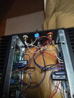
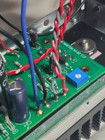
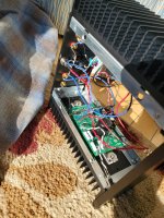
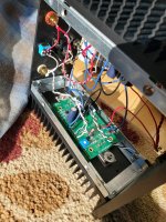
Do you have something shorting to chassis or heatsink underneath the circuit board? It’s worth a look…
Can you post a photo or two so we can see all the current wiring?
We’ll get this going, I promise.
All the DC voltage measurements are good, so all the transistors are operative.
Do you have something shorting to chassis or heatsink underneath the circuit board? It’s worth a look…
Can you post a photo or two so we can see all the current wiring?
We’ll get this going, I promise.
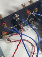
What would cause both speaker binding posts to be . I know the positive one should be grounded.
Last edited:
- Home
- The diyAudio Store
- Amp Camp Amp Kit 1.6/1.8