So massive differences round about 30 seconds in on your recording assuming that the sound at 30 seconds and at 32 seconds is meant to be the same.
I've no immediate answer to that I'm afraid... it really needs looking at with a scope to see what is happening.
Have you got a frequency sweep test tone? If not I can create one in a couple of minutes and attach it. It would be an MP3 file.
What I'm thinking is you could record the sweep at say around 0.5 to 1 watt output. That will be very loud to you but safe for the speakers. We could then analyse that and compare channels. You could use the mic initially and I would say use only one speaker and one input feed and swap those between channels so we get a true 'amp only test'.
So you would have two recordings, one of left channel and one of right. We can then look at that and see if there is any deviation.
This shows what I think are the two treble parts. One is much higher than the other in amplitude and I've also quickly plotted the spectrum of both. Its very strange for that to be an amp kind of problem... interesting.
It will be tomorrow when I look in again 🙂


It will be tomorrow when I look in again 🙂
Here's continuous & stepped sine sweeps from that Outlier Audio youtube test clip. Really highlights the issue in upper-midrange and beyond. Left channel is first and there's some background noise from the road unfortunately.
Oops, must have copied the link without turning on sharing. Should work now. Thanks for taking a look.
It looks very strange and unfortunately isn't giving enough clues at this point. This is your track, so if we say that the midpoint is where it switches channels... well it all just looks really really strange.
Can you confirm you have used one single RCA feed and just one speaker so that we can 100% rule out anything other than the amp? Signal handling faults (uneven and weird response) are almost unknown tbh. I can't begin to imagine what is happening here although I know for sure a scope would show things much more clearly.
So you really are getting into oscilloscope territory here.
If you could feed a known good sweep into the amp (not one from YouTube 😉) and connect the output of the amp to your PC line in and record that then we might have more of a chance. You would need to leave the speaker connected as a load and you would need an attenuator on the line in.
I've attached a 192kbps MP3 100Hz to 18kHz sweep in case it is any use.

The frequency sweep would (should) look like this, a constant amplitude across the frequency range. If we zoom in we see the sine.


Can you confirm you have used one single RCA feed and just one speaker so that we can 100% rule out anything other than the amp? Signal handling faults (uneven and weird response) are almost unknown tbh. I can't begin to imagine what is happening here although I know for sure a scope would show things much more clearly.
So you really are getting into oscilloscope territory here.
If you could feed a known good sweep into the amp (not one from YouTube 😉) and connect the output of the amp to your PC line in and record that then we might have more of a chance. You would need to leave the speaker connected as a load and you would need an attenuator on the line in.
I've attached a 192kbps MP3 100Hz to 18kHz sweep in case it is any use.
The frequency sweep would (should) look like this, a constant amplitude across the frequency range. If we zoom in we see the sine.
Thanks Mooly, should have a moment to try this in the next few days. Just want to check the setup so you get what you need.
I'll run a single RCA (from my DAC at a fixed source volume) into the right channel first, record the test tone, then switch the same RCA into the left channel and connect the same speaker to the left speaker outputs, correct?
I just picked up fresh speaker wire, banana plugs, and a longer RCA to make all the swapping around a bit easier.
In the realm of further inexplicability, the channel imbalance now indeed reversed after the Q4 swap. So, the right side (where the suspect Q4 now lives) is quite a bit lower in output volume. I don't know if I just wasn't hearing it correctly earlier, but it's now very evident. There's also worse popping when nothing's being output from the source. The mystery continues.
That all sounds OK.Just want to check the setup so you get what you need.
Remember that the speaker sockets (red and black) on an ACA are reversed by design. Make sure that the ground of the lead to the PC really does go to the speaker terminal that is grounded in the amp which should be the red on.
So like this. R1 and R2 may not be needed if you keep the level low. If it overloads the PC input you need it. R1 and R2 can be any reasonable combination such as 10k for R1 and 1k for R2.
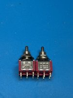
Picked up a pre-built ACA and was wanting to order some parts before it got here to do rework on it. What is the stock size of C2? Are C3/C4 still Silmic II? Also, does anyone have a Mouser part # for the V1.8 on-off-on paddle switch (I don't want to place an order to PE for just a couple of those)?
Found C2. 10mm x 20mm Panasonic EB series. I have one Silmic on hand so may need to find some others. I’d just like the newer amp to match my older one.
The switch I’m still looking for. I do have a couple of DPDT Taiway on-off-on short bat switches rated at 2A/250v, 5A/125v.
The switch I’m still looking for. I do have a couple of DPDT Taiway on-off-on short bat switches rated at 2A/250v, 5A/125v.
Attachments
From https://guides.diyaudio.com/Guide/Amp+Camp+Amp+V1.8+Change+Information/10
I have two ACAs, one v1.6 and one v1.8, I'm wondering if there's any way to get an updated back panel (with the printing the v1.6 lacks) so I can update my v1.6 to match the v1.8 ?
I've been combing through the forums but haven't had any lucking finding out more...
Was this "make-up kit" ever available?PS V1.5/V1.6 owners: In October will be offering V1.5/V1.6 to V1.8 make-up kits for builders who have already built a V1.6 (or earlier) and want to bring it up to V1.8 specification (or build matching monos). We'll email you when they are available.
I have two ACAs, one v1.6 and one v1.8, I'm wondering if there's any way to get an updated back panel (with the printing the v1.6 lacks) so I can update my v1.6 to match the v1.8 ?
I've been combing through the forums but haven't had any lucking finding out more...
Somewhat surprised that there has been no activity here for almost two months. Did nopajoe ever get his issues resolved? Seems a common problem is bad solder joints and wiring mistakes. I am surprised by the graphic in post #1,290. How is someone unfamiliar with the amp going to get the speaker connections right? Doing as much reading as I can before starting. Will be using eutectic solder and a digital soldering station. Is there a multi meter out there that comes with good instructions and is relatively intuitive in use? My HF one is rather crappy. It is unfortunate that Radio Shack went under as they were a local source for electronic parts. I surely hope I can avoid any serious hard to solve problems with my build which should start in earnest in a couple days.
Was looking for the legend for the color codes on the resistor tape. Other than that, I think I have it doped out. 👍 My HF multi meter is going to do the trick ( was able to meas/find the 39k resistors with it. Going to go with the printed values on the bigger 3W sky blue ones.
Last edited:
The key to the color codes is on the sheet of paper included in the kits. Do you have that? it’s printed on both sides
However you MUST also measure them to be sure. Too much possible error otherwise.
The values you measure won’t be exactly what the value is on the schematic diagram, but close enough
to ID the correct ones. The most common error is overlooking the “K” in your meter display.
Since that means “X 1000” that’s gonna really mess things up!
Yes , just use the labeled value on the light blue or pink 3watt resistors
Last edited:
And use and follow the build guides and all of the instructions. For example, each build guide says to be meticulous about which parts are installed when, and to keep a print out of the schematic and parts list with you and check things off as you go. Double check BEFORE you solder and take your time soldering. Soldering is one of those things in life that gives you a do-over most times - so get it right or keep trying until you do. Also get a decent multi-meter - spend a little cash and get a decent one like a Fluke so that it can test L, R and C. This way you can get into the habit of measuring ALL of the parts you get in the kits so you can convince yourself that you have inserted the right one into the right space on the board.98% of builders have zero issues. Go slow, enjoy the process, you’ll be fine!
😎
People like @6L6 go to great lengths to create the build guides. If you follow them to the letter, you are very likely going to be fine - especially on the ACAs.
And after all that, if you get stuck, ask on the forums. There are a lot of people here like myself that have built over a dozen ACAs over the years and are happy to help.
--Tom

- Home
- The diyAudio Store
- Amp Camp Amp Kit 1.6/1.8