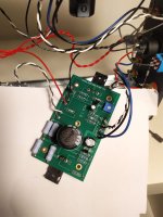
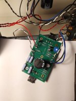
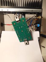
Hi everyone, I have a problem with my ACA V1.8, the right channel does not emit any sound, and when I try to mesure the voltage to set the bias, the voltage is 0. Could someone help me?
Ok, nothing is jumping out at me but hopefully somebody else will look as well.
Go to step 56 of the guide and do the power off resistance checks and the power on voltage checks as described.
https://guides.diyaudio.com/Guide/Amp+Camp+Amp+V1.6+Build+Guide/5?lang=en
Go to step 56 of the guide and do the power off resistance checks and the power on voltage checks as described.
https://guides.diyaudio.com/Guide/Amp+Camp+Amp+V1.6+Build+Guide/5?lang=en
After the resistance checks maybe reflow the solder joints on Q3. They look a bit suspect from the top.
Hi everyone, I have a problem with my ACA V1.8, the right channel does not emit any sound, and when I try to mesure the voltage to set the bias, the voltage is 0. Could someone help me?
Begin with the basics.
Check that you have 24 volts supply on the middle pin of Q2
Assuming that is OK what voltage do you see on each end of R7
Ok, nothing is jumping out at me but hopefully somebody else will look as well.
Go to step 56 of the guide and do the power off resistance checks and the power on voltage checks as described.
https://guides.diyaudio.com/Guide/Amp+Camp+Amp+V1.6+Build+Guide/5?lang=en
10 minutes ago while i was doing the voltage tests I've seen that on Q1 G there was 5 volts (I started asking here because there were 0 Volts before) and so I turned it to 12 by the bias potentiometer and now all works perfectly, I suppose that there is a false contact somewhere, I'll chech all the solderings
Thank you, I'll chech also this one!After the resistance checks maybe reflow the solder joints on Q3. They look a bit suspect from the top.
Good news! Yes, check the solder joints and reflow any that look suspect. Also good to poke the board and components with a wooden or bamboo chopstick or something similar when doing power-on tests to see if there are any loose solder joints.
Yes thanks, I did that too but nothing creaksGood news! Yes, check the solder joints and reflow any that look suspect. Also good to poke the board and components with a wooden or bamboo chopstick or something similar when doing power-on tests to see if there are any loose solder joints.
Hi all, I have built two ACA amps and intended to bridge them for more power (15watts).
The only picture I can find in the V1.6 build guide that refers to a stereo bridged configuration shows the two amps with an XLR cable going into each XLR port.
So how does the signal get in? I use RCA's as I suspect most people do, so does the signal go in via the RCA's and the two XLR's are indeed one cable coming out of one amp and going into the other? If it's not one cable, where does the end of the other XLR cable go?
I can't seem to work this one out from the photos.
Also, what is the benefit of making it a V1.8?
TIA
As far as I know the 1.6 used a 19 volt power supply and the 1.8 uses a 24 volt supply which allows slightly higher voltage swing across the load.
In bridged mode you feed the signal (for one channel, left or right) into just one RCA and the speaker output of that channel is then fed via a resistor into the input of the other channel. The ACA is inverting of phase and so the second channel is automatically 180 phase shifted.
The rear panel switch selects that mode.
Thanks I've seen that diagram, but still don't understand. I could easily wire that up as in the 1.8 diagram but only if there's a perceived benefit which I'm yet to find out about.
What I'll do is take a photo of what I think will give me a bridged (15 watts, stereo) amp and post them here and if I've got it wrong you all can tell me, i'll include a photo of internal wiring as I've done it so far, in respect to the rear panel.
What I'll do is take a photo of what I think will give me a bridged (15 watts, stereo) amp and post them here and if I've got it wrong you all can tell me, i'll include a photo of internal wiring as I've done it so far, in respect to the rear panel.
If anyone is wondering why the holes in the back-probably not necessary but for cooling as I've clad (rather poorly, I'm not bothered) in Walnut veneer.
Above it is an Objective 02 headphone amp doubling as the preamp

Above it is an Objective 02 headphone amp doubling as the preamp
Its really difficult working from pictures 🙂Thanks I've seen that diagram, but still don't understand. I could easily wire that up as in the 1.8 diagram but only if there's a perceived benefit which I'm yet to find out about.
What I'll do is take a photo of what I think will give me a bridged (15 watts, stereo) amp and post them here and if I've got it wrong you all can tell me, i'll include a photo of internal wiring as I've done it so far, in respect to the rear panel.
You should be able to check its ok just by simple tests.
There are three modes you can use a single stereo ACA in.
1/ Normal stereo. The two channels are independent with one used for left and one for right.
2/ Parallel mono. This has the two identical channels in parallel. Each channel receives the same input signal. One RCA is used and the switch feeds the RCA input in use into the other channels input.
3/ Bridged mode. This the mode you seem to want to generate more voltage swing (power) into the speaker.
Your switch should connect the board connection input of the right channel to the speaker output of the left channel via a 39k. The left RCA input feeds the audio for one channel to left channel of the amp. The right RCA socket is left unconnected.
Electrically it has to look like this. The speaker is at the bottom. The 39k (ignore that it says 34k on my diagram) feeds one channels output to the other channels input:
Ah thanks, that's where I was going wrong. There's only one speaker in that diagram, I thought mistakenly that I could twin the two power amps to supply 15watts into two speakers ie. stereo 15 watts per channel.
I guess as long as the gains are identical in both amps that I built I could just run one amp per RCA per speaker in a sort of dual-mono setup with 100% separation.
I am as I suspect, are most who built these amps fairly new to this field and I for one do not understand wiring diagrams, but I can see clearly in that one above that you kindly posted Mooly that there are two amps and one speaker.
That's right, the speaker is fed from across the two 'live' output terminals. There is just one input per complete ACA as here. You will see the output of one channel feeds the input of the other channel. The second channels output is phase shifted by 180 degrees because the ACA is an inverting amplifier. So you have one complete ACA (the two channel amp) for one speaker. Saem setup for the other channel. The separation is 100%
As one channels output goes 'up' the other goes 'down'. The result is you get double the voltage across the speaker at any given moment compared to just one channel on its own. Although the voltage is double, the current available for the speaker remains the same and so that becomes the limiting factor here.

As one channels output goes 'up' the other goes 'down'. The result is you get double the voltage across the speaker at any given moment compared to just one channel on its own. Although the voltage is double, the current available for the speaker remains the same and so that becomes the limiting factor here.
Thanks yet again, especially for bearing with me-my understanding on electronics is quite low, I'm reasonably good at the building part though.
So one last question:
If I do as I suggested and use one amp for just the left channel, and the other amp just for the right channel to get stereo rather than using one ACA on its own, what position does the switch need to be in, and which of the four speaker outputs do I use for each individual speaker on each amp, given that there are four posts?
- Home
- The diyAudio Store
- Amp Camp Amp Kit 1.6/1.8


