Why Two LEDs?
I hope I’m posting in the correct place. I searched but found no answer. Could someone explain why the Amp Camp Amp has provisions for two LEDs? I’ve never known any audio component to have two instead of one. Thanks.
I hope I’m posting in the correct place. I searched but found no answer. Could someone explain why the Amp Camp Amp has provisions for two LEDs? I’ve never known any audio component to have two instead of one. Thanks.
Thanks for the suggestions. Turns out I had gotten sloppy with the RCA soldering and had shorted input to ground. All seems well now.
One more question - does this amp require some time to burn in before sounding it's best?
Steve
One more question - does this amp require some time to burn in before sounding it's best?
Steve
Originally, the Amp Camp Amp was created to hold each channel in a different case with two PSUs. Each channel had its own LED, obviously.I hope I’m posting in the correct place. I searched but found no answer. Could someone explain why the Amp Camp Amp has provisions for two LEDs? I’ve never known any audio component to have two instead of one. Thanks.
Afterwards, they created the 'single case' version but I guess the 'each channel with it's own LED' approach simply 'endured'? Or was it intended...
... if you consider the 'source' of the design:
FIRST WATT PRODUCTS
Most First Watt products (if not all) actually have tow different LEDs... one for each channel. The J2 and the M2 featured in the link above both have two LEDs.
I personally like them a lot. If you have a perfectly separate two channel topology with nothing shared, why not! 🙂
Rafa.
Glad to hear things are working!...One more question - does this amp require some time to burn in before sounding it's best?
Steve
Some say it does... I can attest that sound changed a bit during the course of the first week... but sound was already 'almost there' right off the start.
If you find there is something you don't like a lot... I don't think it's going to change much. I find it that 'burn in' is very subtle, if at all noticeable.
What IS noticeable is the cool vs. warm sound. To do critical listening, allow for some time (20 minutes?) to 'judge' the color of the ACA.
Hope this helps,
Rafa.
I hope I’m posting in the correct place. I searched but found no answer. Could someone explain why the Amp Camp Amp has provisions for two LEDs? I’ve never known any audio component to have two instead of one. Thanks.
There's one LED for each board. So, in stereo mode that's one LED for each channel.
And in monoblock mode there are also two LEDs, one for each board and now only one speaker to it. So I think stereo has nothing to do with it! 😛
I have some questions about the parallel mono mode described in the "ACA v1.6 Operation Modes" document.
Firstly, I believe it requires Y splitter RCA cables and also Y speaker cables. The RCAs split the signal before the amp and the speaker cables rejoin it after the amp. Is that correct?
Secondly, my current pre-amp (a Marantz SR5011 receiver) has an extra pair of RCA outputs that can be used for a variety of purposes. One possible purpose is to have these extra outputs send the same signal as front-left and front-right channels, so that you can go off to two power amps and bi-amp your front two channels without using Y splitter RCAs. Since these outputs can be used for other tasks too (like carrying the rear channel signals in a 7.1 setup), I believe there are separate electronics behind them - they're not just wired to the main outputs. (Perhaps I'm wrong about this)
My question is: is there an advantage (or disadvantage or neither) to sending two copies of the same signal into an ACA running parallel mono, rather than using just one signal with an RCA splitter?
gwils: No need for Y cables, just follow the method in post #6522 in the ACA main thread. https://www.diyaudio.com/forums/pass-labs/215392-amp-camp-amp-aca-653.html#post5595943
Then just use the 'normal' left and right outputs from your receiver.
Then just use the 'normal' left and right outputs from your receiver.
...this one is easiest to do and understand by Mutuano. It is all external and easily reversible too.
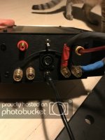
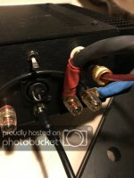
Link the two pins in the XLR socket with a suitable loop or wire as shown. That joins the left and right inputs together.
Link the two Black speaker connections with a wire. (The Red ones are already joined internally.)
If you have wired the rear switch from the build guide step 38, make sure it is Down as in the pictures.
That's it.
Attachments
...Firstly, I believe it requires Y splitter RCA cables and also Y speaker cables. The RCAs split the signal before the amp and the speaker cables rejoin it after the amp. Is that correct?
Yes, this is the right concept. But it can be achieved through several ways. As you can see, shorting pins 2 and 3 from the XLR connector will send the same signal input from one RCA to the other. Or you can 'bridge' them inside.
Same goes with speaker terminals. Yes, they need to be 'combined'. The red ones already are shared ground, so no need. The black ones can be bridged from the outside, the inside or the output wired directly from both channels to a single post if you want the change to be permanent.
...My question is: is there an advantage (or disadvantage or neither) to sending two copies of the same signal into an ACA running parallel mono, rather than using just one signal with an RCA splitter?
If you are sure that they are perfectly equal in voltage, current, EQ, phase, timing, etc., then I don't see a problem with using both outputs. But if they are separate electronics, then I wouldn't risk it, specially with the options suggested here that are benign, and fully reversible from the outside of the case. Why take the chance?
Hope his helps, best regards,
Rafa.
Bridged Mono With XLR Input Only - Questions
I am planning to build ACA bridged mono with XLR input only. My source is DAC which is having balanced outputs and I am planning to run XLR cables between DAC and AmpCamp.
Looking at the ACA v1.6 build guide, I have come up with a simpler connection diagram.

Could anyone please verify whether I am doing it right?
Please note that for both the amp boards, the line input (-ve) terminal is not connected to anything (i.e. open). I am planning to ditch the RCA terminals altogether.
The XLR connector pinout shown in the illustration is the back side of a female XLR connector (i.e. back side inside cabinet)
I have posted same query here as well.
Cheers,
Saikat
I am planning to build ACA bridged mono with XLR input only. My source is DAC which is having balanced outputs and I am planning to run XLR cables between DAC and AmpCamp.
Looking at the ACA v1.6 build guide, I have come up with a simpler connection diagram.
Could anyone please verify whether I am doing it right?
Please note that for both the amp boards, the line input (-ve) terminal is not connected to anything (i.e. open). I am planning to ditch the RCA terminals altogether.
The XLR connector pinout shown in the illustration is the back side of a female XLR connector (i.e. back side inside cabinet)
I have posted same query here as well.
Cheers,
Saikat
Saikat,
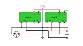
Correct. Your diagram makes electrical sense given your design parameters, i.e. XLR input ONLY and bridged monoblock ONLY with a design (SE Class solid state) whose phase needs to be reversed on the output as it is cap coupled.
It also follows this diagram:

I have tested the above with an Oppo 205 (differential outputs) and it works fine.
সন্ধ্যাটি ভালো কাটুক (transl.= Have a nice evening)
Best,
Anand.
Correct. Your diagram makes electrical sense given your design parameters, i.e. XLR input ONLY and bridged monoblock ONLY with a design (SE Class solid state) whose phase needs to be reversed on the output as it is cap coupled.
It also follows this diagram:
I have tested the above with an Oppo 205 (differential outputs) and it works fine.
সন্ধ্যাটি ভালো কাটুক (transl.= Have a nice evening)
Best,
Anand.
Last edited:
I am planning to build ACA bridged mono with XLR input only. My source is DAC which is having balanced outputs and I am planning to run XLR cables between DAC and AmpCamp.
Looking at the ACA v1.6 build guide, I have come up with a simpler connection diagram.
Could anyone please verify whether I am doing it right?
Please note that for both the amp boards, the line input (-ve) terminal is not connected to anything (i.e. open). I am planning to ditch the RCA terminals altogether.
The XLR connector pinout shown in the illustration is the back side of a female XLR connector (i.e. back side inside cabinet)
I have posted same query here as well.
Cheers,
Saikat
I believe the image was removed from my earlier post. Reposting the image.
Attachments
Saikat,
Correct. Your diagram makes electrical sense given your design parameters, i.e. XLR input ONLY and bridged monoblock ONLY with a design (SE Class solid state) whose phase needs to be reversed on the output as it is cap coupled.
It also follows this diagram:
I have tested the above with an Oppo 205 (differential outputs) and it works fine.
সন্ধ্যাটি ভালো কাটুক (transl.= Have a nice evening)
Best,
Anand.
Hi Anand, Thanks a lot for the confirmation.
Cheers,
Saikat
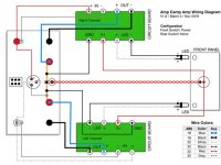
What you have described looks fine to me. Here's the new "Batch 3" wiring diagram for reference.
Hi Jason,
Thanks a lot for the confirmation. I've taken the inspiration from the ACA v1.6 wiring diagram only.
Cheers,
Saikat
Success, question about adjusting the bias
Successfully completed my ACA v 1.6 amp. Thank you all at diyaudiostore for this wonderful kit.
It sounds so beautiful and smooth compared to the Lepy A2020+ which I have used before. I am very happy.
However, I have got a question regarding the bias tuning (step 52 of the build guide). I cannot adjust it better than 12.5 V on both channels. Both pots are approximately in their middle position. What will be the consequence of this? I am thinking of leaving it as is.
Sorry for this question, but my electronics knowledge is a bit rusty.
... However, I have got a question regarding the bias tuning (step 52 of the build guide). I cannot adjust it better than 12.5 V on both channels. Both pots are approximately in their middle position. What will be the consequence of this? I am thinking of leaving it as is.
Hi devize,
Does the voltage on the centre pin of Q1 (where you measure the bias) change when you turn the pot?
Can you get it lower than 12.5 volts - it should really be 12.0 volts?
The pot does not have to be in the middle, just where it gives you 12 volts.
Alan
I could make 11.5V, I just was not able to hit 12V exactly. Would 11.5V be better?
Ist there any harm for the device, if I leave it at 12.5V
Ist there any harm for the device, if I leave it at 12.5V
devize, That's fine then, if the bias is adjustable, it is working to specification.
As long as you get close to 12 volts +/- 0.1 or 0.2 volts there is no problem.
Best let it warm up for 20 minutes and then set it (no speakers or input connected.)
Go and enjoy, Alan
As long as you get close to 12 volts +/- 0.1 or 0.2 volts there is no problem.
Best let it warm up for 20 minutes and then set it (no speakers or input connected.)
Go and enjoy, Alan
Devize, for me, the 'final mile' was less of a 'turn' and more of a 'tap'.
So, when you are nearing your target voltage, give it a slight 'twist' more like a shake rather than a twist BUT without actually feeling the knob turn and wait a few seconds (as you may have figured out already, there is a small delay between your action and the voltage changing). Did it move at all? If not, repeat with a bit more strength.
For me, the voltage changed even it I felt that the knob haven't moved and there was a 'springy' feel to my move.
Sorry I'm lacking all the right words here, but I hope you get the idea. 'Attempt' to turn it without actually feeling the knob move and see if that gives you finer control. For me it did.
Best of lucks and congrats on your build,
Rafa.
- Home
- The diyAudio Store
- Amp Camp Amp Kit 1.6/1.8