Thanks Steve.
Checked the resistors, but they are OK. Had a bad smell at one of the IRFP240.
Check with Volt Meter showed not only false readings, it probably produced a short circuit (some minor flashing at the soldering).
I will change both IRFP240, perhaps too hot at soldering and therefore default?
And: the power supply showed a blinking LED?! Voltmeter says 8,8 instead of 24 Volt??
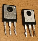
here are the desoldered IRFP240, one looks very "sad":
Checked the resistors, but they are OK. Had a bad smell at one of the IRFP240.
Check with Volt Meter showed not only false readings, it probably produced a short circuit (some minor flashing at the soldering).
I will change both IRFP240, perhaps too hot at soldering and therefore default?
And: the power supply showed a blinking LED?! Voltmeter says 8,8 instead of 24 Volt??
here are the desoldered IRFP240, one looks very "sad":
An externally hosted image should be here but it was not working when we last tested it.
... Had a bad smell at one of the IRFP240.
Check with Volt Meter showed not only false readings, it probably produced a short circuit (some minor flashing at the soldering).
I will change both IRFP240, perhaps too hot at soldering and therefore default?
And: the power supply showed a blinking LED?! Voltmeter says 8,8 instead of 24 Volt??
here are the desoldered IRFP240, one looks very "sad":An externally hosted image should be here but it was not working when we last tested it.
Hi,
Very unlikely to be overheating during soldering.
'Flashing' at the soldering - can you explain? Did you have power on?
Please post some pictures of your build that we all can see. We might be able to help then. (Not all of us have Flikr accounts...) Alan
Received ACA 1.6 batch 2 kit a few months ago but have just now had time to work with it. Have completed all but the wiring.
The wiring diagram in the build guide has following wires:
- thick blue
- thick black
- thin black
- thin red
- thin white
- thin green
but in the package was:
- thick red
- thick black
- thin blue
- thin red
- thin white
- thin green
Thick red replaces thick blue and thin blue replaces thin black?
The wiring diagram in the build guide has following wires:
- thick blue
- thick black
- thin black
- thin red
- thin white
- thin green
but in the package was:
- thick red
- thick black
- thin blue
- thin red
- thin white
- thin green
Thick red replaces thick blue and thin blue replaces thin black?
Received ACA 1.6 batch 2 kit a few months ago but have just now had time to work with it. Have completed all but the wiring.
... Thick red replaces thick blue and thin blue replaces thin black?
Yes. That is fine. (I think there has been some variation in colours from time to time. Keep the thick wires for the speaker connections and all will be well.)
Alan
Hi,
Very unlikely to be overheating during soldering.
'Flashing' at the soldering - can you explain? Did you have power on?
Please post some pictures of your build that we all can see. We might be able to help then. (Not all of us have Flikr accounts...) Alan
You do know that if you plug the meter probes directly onto the power supply with nothing attached you’ll short circuit the PSU and trip it’s protection circuits? I’m guessing that’s what’s making the PSU blink. If your soldering iron is on the puny side leaving it on any component for a long time isn’t healthy. I’ve got a thermostat controlled iron and cranked it up a lot just for the main transistors they certainly suck some heat out of the iron.
You do know that if you plug the meter probes directly onto the power supply with nothing attached you’ll short circuit the PSU and trip it’s protection circuits? I’m guessing that’s what’s making the PSU blink.
Steve, not sure if you intended this for me or eyspot?
Any way, I think you have a typo in your first comment.
You cannot 'short circuit' the PSU when measuring voltage unless you accidentally touch the probes together (a short circuit) or have the meter on the Current (Amps) range by mistake. The ACA power supply is as you say protected so will 'blink' if shorted by a fault.
... If your soldering iron is on the puny side leaving it on any component for a long time isn’t healthy. I’ve got a thermostat controlled iron and cranked it up a lot just for the main transistors they certainly suck some heat out of the iron.
Yes, not good to leave the iron on any device too long. But the reason I am doubtful about eyspot damaging his IRFP240 by over heating whilst soldering it is because it is bolted to the heatsink, which keeps the junction temperature down and is one reason it takes a little longer to solder them in.
I was more concerned that he says 'flashing at the soldering', which either means there is a static discharge or there is power in the circuit during soldering. Either could easily pop the MOSFET...
Alan
Sorry for my bad english.
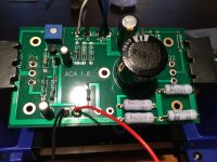
I measured as described in troubleshooting the board, but I ve got not the described values.
Instead of that, while measuring with voltmeter, there was a sparkling at the soldered feet of the MOSFET (no measuring during soldering). Overheating maybe, because Ive soldered the Mosfet before connecting it to the heatsinks. And they "look" like cooked.
After that I recognized the PSU blinking. (Voltmeter shows only 9 Volt entering the boards) I unsoldered the defect board and now the remained board works flawless and no more PSU blinking./Users/druweschuetz/Desktop/IMG_0602.jpg
I didn´t measure the PSU directly. I didn't measure while soldering.
how to attache a jpeg?
uwe
Attachments
Sorry for my bad english.
I measured as described in troubleshooting the board, but I ve got not the described values.
Instead of that, while measuring with voltmeter, there was a sparkling at the soldered feet of the MOSFET (no measuring during soldering). Overheating maybe, because Ive soldered the Mosfet before connecting it to the heatsinks. And they "look" like cooked.
After that I recognized the PSU blinking. (Voltmeter shows only 9 Volt entering the boards) I unsoldered the defect board and now the remained board works flawless and no more PSU blinking
I didn´t measure the PSU directly. I didn't measure while soldering.
how to attache a jpeg?
uwe
Hey. Would this one the right exchange part: Vishay IRFP240 MOSFET 1 N-Kanal 150 W TO-247 ?? Any other suggestions. Uwe
Hey. Would this one the right exchange part: Vishay IRFP240 MOSFET 1 N-Kanal 150 W TO-247 ?? Any other suggestions. Uwe
That's perfect.
eyspot,
Your English is not a problem! I understand the fault(s) now.
Yes that is the correct part, replace them both.
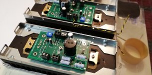
You will have to inspect the 'Keratherm' insulators (brown pads) carefully. One will almost certainly be damaged as well.
When you re-fit the IRFP240s to the heatsinks, do a continuity test from the heat sink to each pin in turn (200 ohms range). They should all measure open circuit.
Then re-fit the board and solder them in.
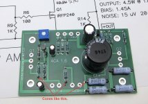
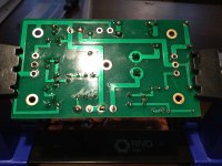
All the components look to be in the correct places, but your soldering is very 'shallow'. The solder normally travels through the holes and forms a small cone round each lead on the top of the board. See the picture from the build guide. Your board should look like this ideally.
Can you post a picture of the underside as well please? It could be a simple poor connection is the original fault.
Alan
Your English is not a problem! I understand the fault(s) now.
Yes that is the correct part, replace them both.
You will have to inspect the 'Keratherm' insulators (brown pads) carefully. One will almost certainly be damaged as well.
When you re-fit the IRFP240s to the heatsinks, do a continuity test from the heat sink to each pin in turn (200 ohms range). They should all measure open circuit.
Then re-fit the board and solder them in.
All the components look to be in the correct places, but your soldering is very 'shallow'. The solder normally travels through the holes and forms a small cone round each lead on the top of the board. See the picture from the build guide. Your board should look like this ideally.
Can you post a picture of the underside as well please? It could be a simple poor connection is the original fault.
Alan
Attachments
Last edited:
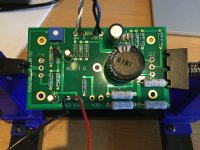
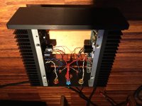
Hi Alan, did new - hope a litte better - desoldering. Built all together, set bias and...
hurray WORKING !!!! thanx, happy 2019, a lot of music..
just ordered a second one, its fun to built, to learn from my mistakes, thanks to the forum members.
The second one I will try to do perfect.......
uwe
hurray WORKING !!!! thanx, happy 2019, a lot of music..
just ordered a second one, its fun to built, to learn from my mistakes, thanks to the forum members.
The second one I will try to do perfect.......
uwe
Attachments
Sorry for my bad english.
Overheating maybe, because Ive soldered the Mosfet before connecting it to the heatsinks. And they "look" like cooked.
uwe
You may have pinpointed the problem.
Possible that that one or more of the Mosfet legs were mechanically stressed enough to cause an internal fault when it was attached to the heatsink.

I successfully completed my build with one minor glitch. After adjusting the bias on both channels 12 volts, one the channels' bias went up to 20 volts after several hours. That side was also running cool. Reflowing the PCB solder joints fixed the issue.
I have tested the amplifier with three different pairs of speakers:
I have tested the amplifier with three different pairs of speakers:
- Vintage LS5/5A, these are 15 ohm speakers
- KEF C35 coaxial speakers, I believe these are 4 ohm speakers
- ELAC Uni-Fi UB5, these are 4 ohm speakers
Another happy person on Earth
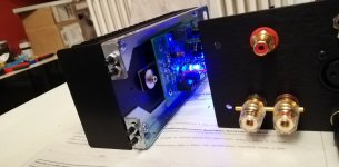
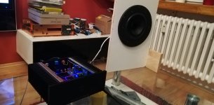
First, much thanks to DIY Audio Store for making these kits available to all, providing a nice looking chassis, and rounding up all the parts and organizing them so well.
I've completed two kits. Fascinating silence without signal on very sensitive speakers. At the moment under testing and burning. The first impression is very good. The sound - clean and detailed and very natural.
Also, much thanks must be given to ampguru Mr Pass for allowing his design to be shared among audiophiles fanatics.🙂
Attachments
First, much thanks to DIY Audio Store for making these kits available to all, providing a nice looking chassis, and rounding up all the parts and organizing them so well.
I've completed two kits. Fascinating silence without signal on very sensitive speakers. At the moment under testing and burning. The first impression is very good. The sound - clean and detailed and very natural.
Also, much thanks must be given to ampguru Mr Pass for allowing his design to be shared among audiophiles fanatics.🙂
It's interesting to see how neat and tidy some peoples kits look compared to others - that looks exceptionally neat 🙂
eyspot,
Your English is not a problem! I understand the fault(s) now.
Yes that is the correct part, replace them both.
You will have to inspect the 'Keratherm' insulators (brown pads) carefully. One will almost certainly be damaged as well.
When you re-fit the IRFP240s to the heatsinks, do a continuity test from the heat sink to each pin in turn (200 ohms range). They should all measure open circuit.
Then re-fit the board and solder them in.
All the components look to be in the correct places, but your soldering is very 'shallow'. The solder normally travels through the holes and forms a small cone round each lead on the top of the board. See the picture from the build guide. Your board should look like this ideally.
Can you post a picture of the underside as well please? It could be a simple poor connection is the original fault.
Alan
That is a very helpful post for novices. I had issues on my first build that were fixed with reflowing solder. I wasn’t familiar with what the top side of the PCB should look like, but I now see that I was skimping on solder as well. Thanks for taking the time to post and explain, Alan
I guys, after assembling my amp, I plug it to speaker and my phone to see if it will work. One channel work fine, but the other was dead. Check the solder, do some resoldering, and now the channel have a sound, but very weak and distorted. I try to adjust the bias after 15 minutes but it limits me to 7V fully open. I measure the voltage according to the voltage chart on the build guide, and pin S of Q4 measure 1V instead of 4.7V and pin D of Q1 measured 7V. Have you any idea what is going wrong ?
- Home
- The diyAudio Store
- Amp Camp Amp Kit 1.6/1.8