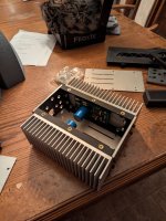
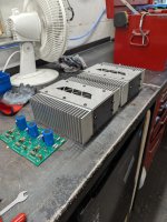
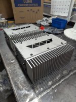
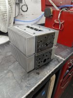
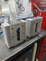
Here we go, 2 completed chassis made using 3D printing for the internal frame and laser cutting for the panels. All the panels could also be 3D printed but I really wanted stainless steel so I had them lasercut through work. The heat sinks came from Amazon.
I love in Canada so buying the chassis from the DIY audio store was going to be extremely expensive to the point I could have probably just bought a very nice used HiFi amp from Canuck Audio Mart. When I get home I will post up all my files and links so anyone can build these.
I'm going to use these on my desktop to power a set of GR Research NX Bravo bookshelf speakers.
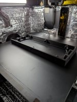
Attachments


Hi. I'm looking for some help.
I've just finished my first aca. When powered up it all worked great. Sound is coming from both channels and for all intents and purposes, it's working.
However only 1 led on the front panel is lit.
I tested the resistor r13 (10k) which is before the led and it is only reading 2.6k whereas the other side is reading correct at 10k.
So I removed it and tested it out of circuit. 10k.
I'm not sure what's happening. Anyone got any ideas? Anything appreciated..
Thanks
orientation of LED, or it's simply cooked while soldering
test it with diode test om DMM, you'll see light ....... or not
test it with diode test om DMM, you'll see light ....... or not
Would this cause the discrepancy I'm seeing on the resistor?orientation of LED,
who cares?
remedy is simple, do it, analyze later when you have all facts
remedy is simple, do it, analyze later when you have all facts
Well that told me didn't it.who cares?
remedy is simple, do it, analyze later when you have all facts
Ok, led is working, (checked with a battery) and is installed in the correct orientation.
I resoldered the connections at the board.
Still not working 😕
I'm not clever enough to know what else it could be.
Have checked all solder joints electrically and nothing is untoward.
I changed the resistor r13 for a new one, purely for good measure. It tested 10k out of circuit, but 2.something as soon as it's installed.
I don't know is the simple answer. Where would I have to measure?what does the circuit measure with the resistor removed?
mabe a solder bridge somewhere?
pics
which exact pcbs you're using, if possible point me to pic of them or article
measure voltage at LED pads
measure voltage at both sides of said resistor, ref. to GND
which exact pcbs you're using, if possible point me to pic of them or article
measure voltage at LED pads
measure voltage at both sides of said resistor, ref. to GND
which exact pcbs you're using, if possible point me to pic of them

OK, so on both boards, I have 18.5v on the + side of the resistor.
On the working board, the other side of the resistor is 2.6v
The non working side is 0.1v
I'll have to whip the board out and have a look at the other side I guess.
Make sure that "upper" side of R13 leg isn't poking through and making contact with the heatsink.
The non working side is 0.1v
lift one end of that resistor and check ohms with ohmmeter, it seems toasted ........ or , what Patrick said - take care of pin length
Thanks for all your help guys, but I give up.
I've taken the led off the board and out of the circuit. The resistor now reads 10k (in circuit) which is correct.
However, I have 18.5v on both sides of the resistor.
I checked the led while it was out, with 3v and it works.
I'm just gonna have to live with the amp only having one led..
Again, I appreciate all your efforts. I don't know what else to look for.
Here is both sides of the board for your interest. My soldering is not perfect, but it's good enough and there are no obvious shorts.
No need to give up just yet, but I understand the frustration.
Trim all the leads first, just to be sure. It's hard to tell, but with non-anodized sinks and the fact that you're not using anything other than the height of the MOSFETs to keep the board raised off the sinks... it's best to be sure. Should take < 30s to give you peace of mind. You've already got it un-mounted, and I see a few that are a bit long.
Barring anything truly strange, there are only a few possibilities. We can use process of elimination all in only one sequence to rule out causes and find the issue. The key is to not change anything until the issue is determined. Do not undo any wiring de-solder anything etc. unless it's called for. You could be dealing with two (or more) things.
1) Bad LED / wiring. I am not sure when you checked the LED (before or after soldering) and how. I can't see how you connected the LED to the fly wire. Rule that out first:
- Put power (a battery or bench PSU maybe) directly to the pads LED+ and LED-. Make sure it's around 9V or more so you can see the light. Make sure that the polarity is correct from the power.
- Does it light?
- Yes - Then LED, wiring, and polarity are good. Somehow power is not getting to the LED. See #2
- No
- Reverse polarity of the power
- Does it light now?
- Yes, then you have the LED wired backwards.
- Reverse the wires at the board. - Stop, you should be fixed.
- No, then it's likely that either the LED is burnt or your wiring is bad / you shorted the legs of the LED.
- Set your DMM to continuity mode and check between the LED + and - pads. Does it beep / show low resistance?
- Yes - you possibly shorted the legs of the LED when doing your wiring. Use heatshrink or a piece of wire insulation between the legs. The other possibly is that you have a short in the wires themselves. I've seen heat melt wire insulation and short the two conductors. Fix that. Stop.
- No - Move on.
- Set your DMM to Diode Test mode and put one probe directly onto each of the LED. Does it light?
- Yes, your wires are ooked up. Fix them.
- No, your LED is burnt. Replace it and take care when soldering to not leave the heat on too long or damage the LED. Stop, hopefully it's fixed.
- Set your DMM to continuity mode and check between the LED + and - pads. Does it beep / show low resistance?
- Yes, then you have the LED wired backwards.
- 2) Power to LED is wrong / bad. Something is changing between scenarios.
- Please confirm how you measured "I have 18.5v on both sides of the resistor". That indicates that you have 0 Ohms resistance / a short. That would be very strange. Hopefully trimming all your leads fixed this if it was the issue. Check it again. That would also have burnt out the LED b/c you'd have no current limiting, but you'd have fixed that above.
- That fixed it? YAY!
- Still no LED light and still measuring 18V5 on both sides of R13? Let us know... something is off, and my wee brain can't come up with a scenario, but other smarter folks can maybe think of something.
- Please confirm how you measured "I have 18.5v on both sides of the resistor". That indicates that you have 0 Ohms resistance / a short. That would be very strange. Hopefully trimming all your leads fixed this if it was the issue. Check it again. That would also have burnt out the LED b/c you'd have no current limiting, but you'd have fixed that above.
Last edited:
@ItsAllInMyHead
Thank you for the thorough troubleshooter. 👍
I've put the amp away for now, but I've read through your post and fairly sure I've eliminated most of the things you mention.
When I lifted the board, there was indeed a blob of solder that had dripped from one of the led + or - pads. It may have come into contact with the heatsink, but the blob must have appeared only yesterday when I added solder to the pads in order to make sure the connection was good, ie I already had the led issue before adding solder and creating the blob. If that makes sense. Either way, I removed it and checked all the other cut leads were nowhere near the heatsink. They aren't.
I checked the led whilst off the board with a battery and it still works. At this point I tried the led, holding the legs to the pads on the board, and both ways around just to be sure (I have removed the led from the wire at this point so it's just the led).
Nothing. 😕
It's all very strange. As you say, the resistor reads 10k (with the led removed) yet there is 18.5v on both sides of it.
That should not happen right?
I'll be getting it back on the bench on Tuesday evening now so I'll be able to confirm more then.
Thanks again for taking the time to help.
@Borats Baby:
Can you describe the exact placement of your both leads on the PCB when you measure 18v on the negative side of LED? I assume the positive DMM lead is on the negative pad, but where is your other DMM lead connected to? Can you confirm that you are doing this measurement with the LED wire leads unsoldered?
Can you describe the exact placement of your both leads on the PCB when you measure 18v on the negative side of LED? I assume the positive DMM lead is on the negative pad, but where is your other DMM lead connected to? Can you confirm that you are doing this measurement with the LED wire leads unsoldered?
If the LED tests operative, you've either got a broken resistor, broken wire, or broken PCB trace, which is causing an open circuit to the LED itself.
Well… if there’s no current draw at all, because the circuit is open, then there will be no voltage drop across the resistor, so it is going to read the same voltage on both sides.
It's all very strange. As you say, the resistor reads 10k (with the led removed) yet there is 18.5v on both sides of it.
That should not happen right?
Well… if there’s no current draw at all, because the circuit is open, then there will be no voltage drop across the resistor, so it is going to read the same voltage on both sides.
Don't do that.... You need the resistor to limit the current. 🙂 You may have tested it appropriately and then smoked it. Once you know it's a good LED with a diode test or a low voltage battery, leave it alone with the confidence that it's a known working good LED.I checked the led whilst off the board with a battery and it still works. At this point I tried the led, holding the legs to the pads on the board, and both ways around just to be sure (I have removed the led from the wire at this point so it's just the led).
Nothing. 😕
On Tuesday -
With the LED / wiring currently removed from the board:
Check that the LED lights with your DMM set to diode test mode at the ends of the wires. Confirm polarity. If not, you possibly smoked the LED w/o a current limiting resistor per above. If so, replace the LED. Make sure that when you connect the DMM to the end of the wires using diode test mode, it lights. Once that is confirmed, pause.
Make sure the board is in place / mounted etc. with all leads trimmed. No LED wiring in place. R13 installed.
Power the circuit
With DMM set to DCV, black probe on GND. Measure voltage at:
V+
LED+
LED-
Top of R13
Bottom of R13
Yes, I realize some of those should be (intentionally) redundant, but you've got something odd and/or I'm missing something.
This is a puzzler....
.............
measure voltage at LED pads
......................
If that has not been done, then do it. Measure the voltage at the LED pads with the LED removed. If the full voltage is present then it is likely there is no problem with the PCB, especially if the dropping resistor also measures the correct resistance with the LED removed.
As for testing the LED with the multimeter in diode or LED mode, be careful. Prolonged testing without a dropping resistor may burn out the LED. I know, I have done it. When I check LEDs with a meter I just touch the probes to the LED momentarily.
Ok.Power the circuit
With DMM set to DCV, black probe on GND. Measure voltage at:
V+.
LED+
LED-
Top of R13
Bottom of R13
Yes, I realize some of those should be (intentionally) redundant, but you've got something odd and/or I'm missing something.
This is a puzzler....
V+. 18.8v
Led+. 18.6v
Led- 0.0v
Top r13 18.6v
Bottom r13 18.6v.
R13 is still measuring 10kohm, before and after power up.
- Home
- Amplifiers
- Pass Labs
- Amp Camp Amp - ACA