Does anyone have a link to the original design explanation article with the schematics intact?
Post #1 of this thread links to the original article, but the images are missing. There's also a link to a pdf - but it's a 404 link.
thanks
Post #1 of this thread links to the original article, but the images are missing. There's also a link to a pdf - but it's a 404 link.
thanks


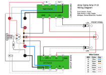
I have now made the second amp with identical boards to the first amp but I have some problems. I am testing with a DBT. One of the boards is motorboating and causing the DBT and LED on the board to pulse rapidly (the DBT flashing) and if a speaker is connected a pulsing rhythm. The other board is not responding at all.I am currently building a second ACA with a view to using both in bridged mode by way of XLRs. I intend to use the wiring shown in the ACA V1.6 guide (page 25 of 42). A Buss is connected between both RED speaker out binding posts and a connection made to it from Pin1 of the XLR (GRD/Shield) pins 2 & 3 are connected to the RCA - IN sockets. Would I be right in saying that if I want to use it in non-bridged mode I would have to desolder one side of the Buss from one of the RED posts?
For this amp I am using 2 Meanwell 4A 24v SMPSs. The voltage is being pulled down on both boards to around 7vdc and the varaible resistors are not operating correctly as I can only reduce the voltage not increase it by twiddling. I assume that the voltage is too low to operate the FETs.
Unfortunately there is no schematic posted for these boards. Any ideas?
If DBT is a a dim bulb tester or limiter, then it will not work with the SMPS. (Each time the SMPS switches on it draws a considerable current, that lights the bulb and drops the mains voltage to below working voltage so switches off, after 'recovery' it switches on again and repeats the cycle...) Try with out the DBT.
If you still get voltage problems, then remove the +ve wire from both boards and see if that gets you 24 volts to the switch.
Replace one +ve wire at a time and see if that board works. Identify the faulty board that way.
The build guide you refer to has the schematic (step 1) and troubleshooting sections (step 56), have a read through. Here: https://guides.diyaudio.com/Guide/Amp+Camp+Amp+V1.6+Build+Guide/5
Hi Alan. Thanks for the info. I never knew that SMPSs did that. The first amp has a linear supply as I had two trannys of the right voltage and some nice regulator boards so the DBT was fine. I will remove it and see how I get on. These are clone boards and I wasn't sure if the schematic on here would be the same. It should be and if I have more problems I will have a look.If DBT is a a dim bulb tester or limiter, then it will not work with the SMPS. (Each time the SMPS switches on it draws a considerable current, that lights the bulb and drops the mains voltage to below working voltage so switches off, after 'recovery' it switches on again and repeats the cycle...) Try with out the DBT.
If you still get voltage problems, then remove the +ve wire from both boards and see if that gets you 24 volts to the switch.
Replace one +ve wire at a time and see if that board works. Identify the faulty board that way.
The build guide you refer to has the schematic (step 1) and troubleshooting sections (step 56), have a read through. Here: https://guides.diyaudio.com/Guide/Amp+Camp+Amp+V1.6+Build+Guide/5
Yes they can do that. Most of the switchers test the load at startup and decide whether the loading is unsafe, by pulsing their output at intervals and looking at the voltage and/or current. This approach will charge big filter caps if nothing else is drawing substantial current, but sometimes it won't do both and just cycles through that routine. In the case of the ACA you would want to delay the onset of bias current and/or reduce the filter capacitance or get a heftier supply.
Well I now have one working board 🙂 the one that was motorboating. The variable resistor now allows the bias to be adjusted.The other one.....needs some investigation as I still cannot adjust the bias.
So if I am building this as a dedicated bridged mono-block with unbalanced RCA's, the left RCA jack positive goes to the left side positive in, and the left output negative goes to the right side positive in via the 39k resistor? So the left out via 39k resistor is the inverted signal to drive the right side?
And if I drive the mono-blocks via B1's I can use the positive output to positive speaker terminal so the B1 inverting is counteracted by the ACA inverting (not grounding the negative outs)?
And if I drive the mono-blocks via B1's I can use the positive output to positive speaker terminal so the B1 inverting is counteracted by the ACA inverting (not grounding the negative outs)?
Attachments
I replaced P1 on the non-working board but am still not able to get more than 7.5 volts at the test poinr. PS is 24v. I have checked that all the components are the correct value and orientation. Could it a dodgy 2SK or ZTX?Well I now have one working board 🙂 the one that was motorboating. The variable resistor now allows the bias to be adjusted.The other one.....needs some investigation as I still cannot adjust the bias.
What other resistance and voltages checks have you made? Perhaps you have a poor solder joint or bridged track?
Maybe post good pictures of the 'good' board and the 'bad' board we may see something.
Maybe post good pictures of the 'good' board and the 'bad' board we may see something.
I went over both boards and reflowed all the solder points and I have checked that there are no bridges, but I will check again. I will take some pics tomorrow and post them. Thanks. Rob.What other resistance and voltages checks have you made? Perhaps you have a poor solder joint or bridged track?
Maybe post good pictures of the 'good' board and the 'bad' board we may see something.
PS I will also do some voltage checks.
Yes, post pictures.
And check that the PS voltage is at the board. Also measure the voltage at the two locations (R6 and R10) relative to Ground. When the pot is turned, do these voltages change and does the Test Point voltage change?
This is to check that the 2SK170 is working properly.
And check that the PS voltage is at the board. Also measure the voltage at the two locations (R6 and R10) relative to Ground. When the pot is turned, do these voltages change and does the Test Point voltage change?
This is to check that the 2SK170 is working properly.
Attachments
Last edited:
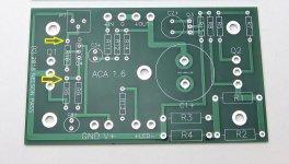
I have done some voltage measurements and before I go any futher and remove the FETs for the resistance scheck I would welcome any comments. I attach a pic of the bad board.I went over both boards and reflowed all the solder points and I have checked that there are no bridges, but I will check again. I will take some pics tomorrow and post them. Thanks. Rob.
PS I will also do some voltage checks.
I have designated the IRFP240 on the left of the board as Q2 (that is how i see it from the schematic but I could be wrong)
Readings of Q2
G. 435mv
D. 7.2v
S 0v
Q1
G. 9.17v
D. 24v
S. 7.2
Umm,
Sorry but the picture is too fuzzy to make much out. Only question would be is the ZTX450 in the right way round, I cannot tell?
I have seen those boards before and some are mirror images of each other, if that is the case be careful to check the component locations very carefully. From your measurements that board has Q1 on the Left. (Q1 S is at 0 volts and Q2 D is at 24 volts.)
You need to measure round the fet K170 next, you need 24 volts on the Drain, about 4.1 to 4.7 volts on the Source and 3.5 to 4.1 volts on the Gate, the source voltage should appear on the Gate of Q1.
Where did you get the K170s from?
Hi Alan. The ZTX is on the right way round as is the K170. I will measure it. The board and parts came as a kit. As I built the first amp from an identical kit I thought I was in luck and would try another. Maybe not a good idea. I have got may hours on the first amp kit from the same supplier and it is superb.
From your measurements that board has Q1 on the Left. (Q1 S is at 0 volts and Q2 D is at 24 volts. Ok, I wasn't sure.
Thanks for your input.
From your measurements that board has Q1 on the Left. (Q1 S is at 0 volts and Q2 D is at 24 volts. Ok, I wasn't sure.
Thanks for your input.
- Home
- Amplifiers
- Pass Labs
- Amp Camp Amp - ACA