Rafa,
Others here can refine my suggestion, but I imagine that you can make sinks that suffice for half of your need work with (very quiet) fans. DC or AC fans slowed way down with resistance should work very well.
Skip
Others here can refine my suggestion, but I imagine that you can make sinks that suffice for half of your need work with (very quiet) fans. DC or AC fans slowed way down with resistance should work very well.
Skip
Ok, I believe I am going to go with the Heat Sinks I posted earlier (http://disti-assets.s3.amazonaws.com/straightroadelectronics/files/datasheets/23768.pdf).
I believe that if I build the case in a way that it is physically touching as much of the heatsink as possible, I can use the entire case (hopefully aluminum) to act as 'secondary' heat sink.
In aim to accomplish that, I was thinking something like this:

Given the size and shape of the heat-sinks, there is no way to attach the PCB to them, I am going to have to mount the MOSFETs to the heat sink and then with cables to the PCB.
For that, I have envisioned three options:
So, the finished project could look something like this:

(This is a 3D rendering, probably my mechanical skills are far less precise and fine, but here's to hoping 😱 )
What do you guys think? Any insight as to which would be the best approach? Thanks!
Best regards,
Rafa.
I believe that if I build the case in a way that it is physically touching as much of the heatsink as possible, I can use the entire case (hopefully aluminum) to act as 'secondary' heat sink.
In aim to accomplish that, I was thinking something like this:
Given the size and shape of the heat-sinks, there is no way to attach the PCB to them, I am going to have to mount the MOSFETs to the heat sink and then with cables to the PCB.
For that, I have envisioned three options:
- Top: PCBs installed at the back and to the bottom of the case. This allows for the shortest cables from inputs to outputs, as well as the cables to the MOSFETs going 'forward' into the heatsinks. Only long cables in this scenario would be the LEDs. The only problem I foresee here is that the PCBs and the electric intake could be too close. Is this an issue?
- Bottom left: PCBs installed also at the bottom but this time up front. This has the advantage of taking the PCBs as far as possible from the electric input, but it makes for long(ish) cables between in -> PCB -> out (they would be 20cm long each)
- Bottom Right: Same scenario but with PCBs mounted on the sides. I'm not sure if there is an advantage of mounting the PCBs vertically. Are they? This means that the case needs to be quite loner (albeit it can be a bit narrower). Not sure this is the right way to do this. Also this scenario could be done with the PCBs to the back if someone thinks that is useful.
So, the finished project could look something like this:
(This is a 3D rendering, probably my mechanical skills are far less precise and fine, but here's to hoping 😱 )
What do you guys think? Any insight as to which would be the best approach? Thanks!
Best regards,
Rafa.
Thanks,Rafa,
Others here can refine my suggestion, but I imagine that you can make sinks that suffice for half of your need work with (very quiet) fans. DC or AC fans slowed way down with resistance should work very well.
Skip
I was thinking about this, but discarded the idea due to the fact that they may introduce unwanted noise, vibration and all sorts of complications. But if that is not the case, then I am all open to such an option. I have some nice ultra quiet fans I bought for my computer CPU water cooler that may work.
I'll certainly look into it. Thanks.
Rafa.
I am interested in doing a linear supply for my build on the new kit ACA 1.6 in a balanced mono configuration separate supplies for each mono block. I already have numerous toroidal transformers that should work with this kit any one else going this way as well? Like to hear any thoughts on this
There’s no disadvantage with making a linear supply, and it may possibly be better. Build with the supplied psu first to get everything operative, tested, and working, and then give the linear a try.
It could be interesting to hear Nelson Pass if they consider making a factory PassLab or FirstWatt amp using SM PSU and if they don't consider it......why.
Is it maybe because people will consider this as a step back or is a linear PSU still the best technical solution?
Is it maybe because people will consider this as a step back or is a linear PSU still the best technical solution?
Forgive me if this has been asked before but I can't find it.... I've replaced C1 with a smaller PP cap as I don't need full response, is there anything to be gained by replacing C3 with a good film cap?
If so whats the best type for audio input?
Thanks
If so whats the best type for audio input?
Thanks
which type - I'm always choosing exactly one which is rattling my cage in least amount 🙂
besides C3 decreasing value , if you din't need full spectrum (down) , you can also decrease output cap (C1) , possibly replacing it with type adequate for your cage
my preferences are always MKC for small values , proper motor run cap for bigger values , bypassed with MKC just for heck of it
besides C3 decreasing value , if you din't need full spectrum (down) , you can also decrease output cap (C1) , possibly replacing it with type adequate for your cage
my preferences are always MKC for small values , proper motor run cap for bigger values , bypassed with MKC just for heck of it
There’s no disadvantage with making a linear supply, and it may possibly be better. Build with the supplied psu first to get everything operative, tested, and working, and then give the linear a try.
and even if you "just so happen to have" most of the requisite components for a liner supply in your parts bin, they will have quite likely initially and ultimately cost more than the SMPS
After reading this just to hear if I could tell any difference. Used my mega clean linear bench supply on my ACA. Can't say I heard any difference. Both methods of supplying DC sound fantastic!
good to know - I mean if you could afford the initial and maintenance cost, running on battery packs could well be the "cleanest" sounding supply available?
except of course for the environmental footprint of the manufacturing supply chain of the batteries, then there's the source of the power to charge them, then .... something
except of course for the environmental footprint of the manufacturing supply chain of the batteries, then there's the source of the power to charge them, then .... something
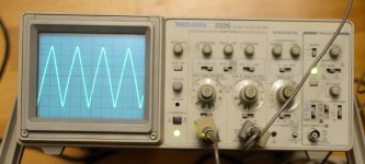
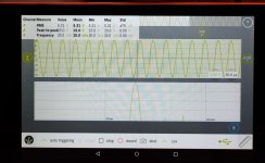
I made one more measurement on the ACA this evening. Tomorrow it will be the other unit. I also found the error on my new lap PSU so I now have two working channels. The scope picture shows a 20 kHz triangle in 4.1 ohm load (2V/div). It looks OK?
Attachments

Of course if you have all the perquisite parts to assemble a proper power supply that would give a savings of $100.00 in Lou of the switchers. In Nelson's article of Audio Amateur 3/94 (The Return of ZEN) he incorporated a pi Filter into the previous filtering in essence a 1 or 2mH air core coil and 2 additional 10kuf caps after the coil. This old ZEN design appears to share more similarities then not with the Amp Camp Amp from what I can tell. So his second iteration accordantly provide a reduction of 26db hum and made the supply improved on other fronts as well.
Last edited:
Looks beautiful!
Time to try some music.
Yes, I could try to hook it up using the lab PSU to power it.
Maybe I will do it when the 2nd unit is up and running.
In the moment my 300B is playing.
Tried in a period to use a big SS amp to drive the 15" woofers but after a while I preferred the sound of the 300B alone. It gives a much better integration of the bass sound. It was for preparation if ACA was not strong enough to drive the 15" woofers. But if 300B can......why not the ACA. It will be my starting point to see how it goes.
Hello,
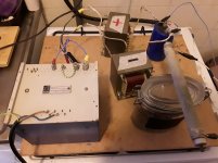
For those people willing to try a choke input power supply i found a surplus store in the Netherlands that has an old big and heavy power transformer from Philips in stock. It is to heavy to send outside Europe ( 11,5 kilograms) . There is 110 210 220 and 238 primary and a 11,6 v 25A and a 23,2 v 10A which i put in series. There is a screen between primary and secundairy winding. I use two 0,5 ohm dcr chokes right after the diodes. Of course you need to use a choke with higher dcr like the ll2733 from lundahl to get a lower dc voltage. I get around 27,8 volts with a 1,8 A load. Using the 210 input while input is 230 volts here. Because i need more than 24 volts for my amp.
So if you are willing to use another choke and are located in Europe it could be nice.
Can also wait for Meper to finish his choke input.
Greetings Eduard
Ps google for elektrodump and you will find the transformer. He has some kemet peh200 47000 63volts caps too. I bought 40 volts caps at mouser because i had limited space
Attachments
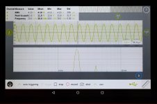
I tried my Labnation digital scope which has a FFT analyzer to see what such a cheap scope can show. With 4.1 ohm load the dominant distortion is 2nd harmonic but with 8.2 ohm load 3rd harmonic is the most dominant. If I turn input signal down a bit the distortion goes below what the scope can show and maybe 2nd harmonic is dominant at lower levels. Signal is a 20 kHz sinus. I normally play well below 1W in average. But now I have something I can compare with when the other unit is tested. The FFT scale is dB so it is logarithmic.
Attachments
After reading this just to hear if I could tell any difference. Used my mega clean linear bench supply on my ACA. Can't say I heard any difference. Both methods of supplying DC sound fantastic!
Hello,
In the past the French l'audiophile magazine published a lot on power supplies. Most of their circuits were class A designs asking for currents similar to the ACA. Most of the time they prefered passive power supplies usually CRC or CLC.
I prefer LCLC or LCRC even for my class D home cinema 2.1 gear.
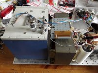
The power supply now being used replaced 2 12 volt lead batteries mounted in series. The batteries had to be replaced because of age and the big transformer, 2 128 mH ( bought from a Belgian member here), a lundahl LL2733 and some Kemet peh200 caps were cheaper than 2 big new batteries.
Greetings, Eduard
- Home
- Amplifiers
- Pass Labs
- Amp Camp Amp - ACA