I will add, that I know it is exciting to try and get your project working, but I would kindly suggest you watch a few soldering videos, and if possible find a practice board to work on.
As others have mentioned, a lot of it revolves around your soldering iron (tip size and wattage mainly) and type of solder you are using, the cleanliness of leads and board (before soldering) and use of flux. The flux is usually provided from flux core solders, but you can also buy liquid flux to help.
Also properly cleaning and tinning of your soldering tip is important. If you don't already have one get one of those Brillo pad type of tip cleaners and use it every time you solder a joint.

the solder sold by the diyAudio store is wonderful stuff.
Hi,
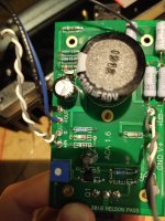
This is my first amplifier build so excuse the questions but I just finished putting it together this afternoon. I plugged it in and saw some smoke. I tried a few things but kept seeing smoke coming from mosfet Q2. After a while, the LEDs started flashing on and off. I read elsewhere that the power supply goes into protection mode when there is a short and oscillates between 24v and 5v. I then found a short on one of the boards and I think one or both of the IRFP240 mosfets are now dead.
Not sure what the best plan of action is. I guess I should order some more of those mosfets and hopefully that will resolve the issue, are any other components likely to have been damaged?
Any suggestions are welcome.
I've attached some pictures of that board.
Attachments
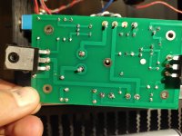

I've removed it now and stupidly didn't take a picture... It was a piece of excess wire on the underside of the PCB and I'm pretty sure it was connecting the ground at the LED to the trace between R3 and R4
That might kill Q2 perhaps.
Do resistance checks (especially round Q1 and Q2) on the board as per the build guide 'trouble shooting' step 56, it might give another clue. https://guides.diyaudio.com/Guide/Amp+Camp+Amp+V1.6+Build+Guide/5#s145
Do resistance checks (especially round Q1 and Q2) on the board as per the build guide 'trouble shooting' step 56, it might give another clue. https://guides.diyaudio.com/Guide/Amp+Camp+Amp+V1.6+Build+Guide/5#s145
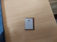
Thanks, just did that and mostly seem to be alright especially around Q1 and Q2. I just checked the keratherm insulation and here are two pictures of the one under Q2. Do you think that tear could be enough to have created a short?
Attachments
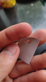
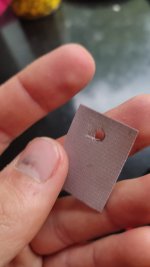
The metal tab on Q2 is connected directly to the Drain. If it was shorted to the heatsink then it would short out the 24volt line and give the pulsing symptom you describe.
That is a strange tear and you need to replace it. Is the black ring from Q2 or a burn mark? Any stray solder blobs or loose strands cause shorts, be meticulous on re-assembly. Check with your meter that it is not shorted too.
That is a strange tear and you need to replace it. Is the black ring from Q2 or a burn mark? Any stray solder blobs or loose strands cause shorts, be meticulous on re-assembly. Check with your meter that it is not shorted too.
Okay, I'll take my time on re-assembly and I believe the black ring is a burn mark. I'm based in the UK and I can't find anyone with 86/82 with precut holes in stock but I did find this
https://www.rapidonline.com/Kerafol...9_1651697443_585d3f1ce055a4188fde9e0f091c2491
which I could use to cut suitably sized pads. I gather the mounting hole needs to be precise, do you have any good suggestions for making the hole as precise as possible?
https://www.rapidonline.com/Kerafol...9_1651697443_585d3f1ce055a4188fde9e0f091c2491
which I could use to cut suitably sized pads. I gather the mounting hole needs to be precise, do you have any good suggestions for making the hole as precise as possible?
I use a 1/8" (3mm) hole punch for my insulation/heat transfer material.
But I have never used Kerafol.
But I have never used Kerafol.
That is the same one that I use, although any 1/8" (3mm) paper hole punch that can be purchased from a crafts or stationery store or from Amazon will most likely work.
sal-cats
I've sent you a PM, ''started a conversation''.
Alan
I've sent you a PM, ''started a conversation''.
Alan
Attachments
Last edited:
Hello, I am new to the DIYAudio. I just build two ACA's. In relation to heat. Can I stack them? If not, can an I orient them side by side? They are side by side now. The shared surface side after a few hours stays around 120 deg F.
I definitely would not stack them, that would be asking from trouble long term. Side by side with a decent space between is fine.
Can anyone tell me what effect (good or bad) increasing or decreasing the voltage measured on the drain of Q1 from 10v for 19v PS or 12v for 24volts? I am just curious.
Pa did found sweet spot, how lower ( more active, governor) and upper (follower) mosfets are cooperating
feel free to alter voltage level of output node and inform us

https://www.firstwatt.com/pdf/art_sweet_spot.pdf
feel free to alter voltage level of output node and inform us
https://www.firstwatt.com/pdf/art_sweet_spot.pdf
Thanks for the article, very enlightening. When I first set up my ACA I set the bias at around 10v not realising that for 24v it should have been around 12v. It could be anticipation bias, but I think it sounded sweeter at that voltage. I just wondered if going too far in any direction say 8v or 14v would do any damage.Pa did found sweet spot, how lower ( more active, governor) and upper (follower) mosfets are cooperating
feel free to alter voltage level of output node and inform us
https://www.firstwatt.com/pdf/art_sweet_spot.pdf
- Home
- Amplifiers
- Pass Labs
- Amp Camp Amp - ACA