Allan, the instructions say to run the MOSFETs at half the PSU voltage, so around 12v would be that. 11v was a bit low. Good to know what a difference it can make!
I successfully switched the orientation of the capacitor. Is it possible I damaged that component/ should i replace it?
Unlikely it is damaged unless you left the amp on for a long time and with a speaker connected.
Reverse biased and the cap would pass DC which would also go through the speaker. The current would be limited by the speakers DC resistance and also the voltage on the midpoint of the amp. The would 'reform' when connected correctly.
Your incorrectly fitted parts may have allowed a higher midpoint or a lower and in that latter case the risk is even less.
Allan, the instructions say to run the MOSFETs at half the PSU voltage, so around 12v would be that. 11v was a bit low. Good to know what a difference it can make!
yeah I didn't read them, bad habit of mine. With summer close by think I'll leave it at 50% rail voltage for now.
Spent a good 5 hrs last late yesterday listening to a good mix of music, not one CD sounded out of place where I wanted to change it.
Even heard a couple of things in tracks I'd never heard before, that puts this little amp in amongst some reputed amplifiers.
Having low gain is a huge benefit too, it allowed me to remove the preamp and go direct to ACA from the transport - just to see what my pre sonically adds or subtracts.
Small, light, very capable honest sonics, easy to chuck into the system... I've a new reference amp!
And after yesterdays session, I think its now fair to say this little ACA pushed those ProAc 125s along unbelievably well, I've never heard them sound so sweet and resolving in any of my systems.
A well balanced very capable amp that is so musical its guaranteed to get toes tapping, fantastic
Last edited:
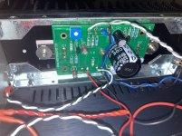
So I've got myself into a bit of a pickle after building this amplifier (v1.8 stereo). The left channel was at a much lower (10-12dB) output than the right channel, even though both were at right around 12.01-12.02V bias and no distortion was detected. Checked/reflowed all solder joints, made sure correct values were in their correct places (both boards identical in band markers for resistors). When completely disconnected from power (this bit has me confused) and both RCAs and speaker leads connected, only the weaker left channel produces an audible hum through a set of fairly large horns (ground loop from inputs all the way through to the outputs?) I even went as far as to completely disconnect the bridge/parallel switch and run straight left/right input into the boards and remove the boards from the heatsinks.
Another oddity, this hum appears when both or *either* RCA input is connected.
I'm honestly not sure where to begin. Attempted using multiple sources to similar effect.
Another oddity, this hum appears when both or *either* RCA input is connected.
I'm honestly not sure where to begin. Attempted using multiple sources to similar effect.
Last edited:
Would be curious to know, if you disconnect both sets of horns, and connect an ohm meter to each set. What do they measure? Just a DC resistance.
Left Horn = ? Ohms DC
Right Horn = ? Ohms DC
You say you hear a hum with no power connected? Is that really what you meant? What are you driving the amp with?
With no speakers connected. Run a tone into both sides of the amp and measure the AC voltage at each speaker terminal.
Pictures of both boards, the back panel both sides might help the ace trouble finders on this site track your issue.
Last question from me is: - do the horns have an amp built into them? Mostly, hums come from ungrounded or electrically unbalanced in some way inputs. Since you indicate this happens with the amp when there is no power. It suggests something upstream from the ACA amp, is feeding the horn.
Would be curious to know, if you disconnect both sets of horns, and connect an ohm meter to each set. What do they measure? Just a DC resistance.
Left Horn = ? Ohms DC
Right Horn = ? Ohms DC
You say you hear a hum with no power connected? Is that really what you meant? What are you driving the amp with?
With no speakers connected. Run a tone into both sides of the amp and measure the AC voltage at each speaker terminal.
Pictures of both boards, the back panel both sides might help the ace trouble finders on this site track your issue.
Last question from me is: - do the horns have an amp built into them? Mostly, hums come from ungrounded or electrically unbalanced in some way inputs. Since you indicate this happens with the amp when there is no power. It suggests something upstream from the ACA amp, is feeding the horn.
Yes, both measure 7.2 ohms DCR on a meter, nominal 8 ohm impedance. Both horns are passive B&C DE75PTN compression drivers mounted in ME60 horns.
The power switch is off and the 24V supply is completely disconnected.
I understand that the hum may be from the source (a DSP), but it makes very little sense that the hum would be audible if connecting *either* the right or left RCA and only having the hum present in the left channel in both cases.
Using a calibrated microphone equidistant to both horns and a sine wave generator (my DMM is finicky with AC voltage measurements, sometimes I wish I never sold my Leader scope), measured response is around 11-12dB down in the left channel at 1kHz. This deviation is reduced as frequency increases to around 3-4dB down at 5kHz. This behavior is not seen using another amplifier as a reference (6SN7/6L6GC tube).
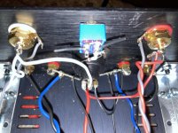
Attached are some photos, forgive the slightly burnt wire ends (top-of-the-board soldering is not my strong suit). Switch in the back was removed from the input circuit to troubleshoot.
Attachments
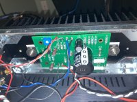

Right out of the hatch, the red RCA input connection looks like there is a solder bridge from the center conductor to ground. It appears that the connection to the XLR connector is lifted, but laying across the center conductor and ground.
Right out of the hatch, the red RCA input connection looks like there is a solder bridge from the center conductor to ground. It appears that the connection to the XLR connector is lifted, but laying across the center conductor and ground.
Hah, apologies. That's a trick of the angle. The blob is some solder on a leftover wire end from a quick snip.
Also, I put the XLR jack in upside-down (or rightside-up depending on if you like pin 3 at the top).
Attached is a photo from a different angle.
Attachments
OK - I see you have disconnected all of the leads to the switch, except the one from the speaker terminal that goes through the high value resistor.
Any chance there is an internal short in that switch that is passing the signal through the resistor to ground?
Any chance there is an internal short in that switch that is passing the signal through the resistor to ground?
OK - I see you have disconnected all of the leads to the switch, except the one from the speaker terminal that goes through the high value resistor.
Any chance there is an internal short in that switch that is passing the signal through the resistor to ground?
The resistor is dangling in free air and not connected. De-soldered the bit of wire going to it from the speaker terminal.
Shorting across Q1 source-drain, P1 and R14 all cut the hum completely, as expected, as it nearly shorts across the speaker outputs at those points (save for that low ~.3 ohm resistance in series for the first two).
Last edited:
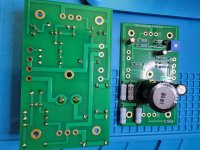
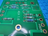
Making progress on my first ACA build. I practiced on a practice board, but of course it doesn't turn out as good when when it counts. When soldering from the bottom, I can't get the solder to flow enough to the other side to cover the pad. Is there a trick to this? If I use more solder, I get balls. I ended up soldering again on the other side to cover the pad, except for the big cap that sits flat. This is only my 2nd time (after the practice board) soldering on a PCB. Any tips or advice is most welcome.
Attachments

Nothing jumps out at me - the -12db and the output hum from either input are indeed perplexing. The last thing I can think of tonight is to lift wires connected to the black speaker posts. One of them may have some kind of partial mechanical failure to ground. It sure seems mechanical - whatever "it" is. There are some other folks here that I am sure will jump in here and get you going. Will keep thinking about it.
So I've got myself into a bit of a pickle after building this amplifier (v1.8 stereo). The left channel was at a much lower (10-12dB) output than the right channel, even though both were at right around 12.01-12.02V bias and no distortion was detected. Checked/reflowed all solder joints, made sure correct values were in their correct places (both boards identical in band markers for resistors). When completely disconnected from power (this bit has me confused) and both RCAs and speaker leads connected, only the weaker left channel produces an audible hum through a set of fairly large horns (ground loop from inputs all the way through to the outputs?) I even went as far as to completely disconnect the bridge/parallel switch and run straight left/right input into the boards and remove the boards from the heatsinks.
Another oddity, this hum appears when both or *either* RCA input is connected.
I'm honestly not sure where to begin. Attempted using multiple sources to similar effect.
First build some shorting RCA plugs and plug them in the input.
That will eliminated the suspicion that other equipment may cause the hum.
Building an RCA Input Shorting Plug -
Shorting plugs – PS Audio
You don't need to follow the instructions re. resistor value exactly, can even replace them with a piece of wire, the idea is to short the input to ground.
Then proceed with more fault finding.
@ Alekk
Start with the easy things.
First measure the resistance from the Red speaker socket to the Black speaker socket, both channels. I should be 500 to 1000Ω. It may take a few seconds to give a full reading.
Second measure the resistance at the RCA sockets. One meter probe on the outer gold ring , the other probe onto the centre pin. That should be about 50KΩ for both channels.
What do you get?
ACA no sound. FIXED!!
Thank you all for your help. Indeed the Q3-Q4 mix up has been corrected and new transistors installed properly and the amp works great! In fact running them mono into the freya tube section is amazing. Not as good as the F7 but holy smokes good. Really good and $650 compared to $3K. Really really good. Thanks
JH
Making progress on my first ACA build. I practiced on a practice board, but of course it doesn't turn out as good when when it counts. When soldering from the bottom, I can't get the solder to flow enough to the other side to cover the pad. Is there a trick to this? If I use more solder, I get balls. I ended up soldering again on the other side to cover the pad, except for the big cap that sits flat. This is only my 2nd time (after the practice board) soldering on a PCB. Any tips or advice is most welcome.
I'm relatively new to this...only started late last year and done maybe 1000 or so total solder connections. As such, if someone who is a real pro wants to correct me...let them!
100% had the same issues you had - and to fix it you need more heat and/or more time. I was very scared to too much heat harming things, but just takes practice to get things 'feeling' right. I use a soldering station (meaning I have a temperature control, and most of what I am doing is at 650 degrees (some would use a little higher, like 700, or maybe a little lower, like 600...but most people seem to be closer to the 700 mark). I am using Kester 24-6040-0027 (you can Google that number to see the details) solder and it is a dream to work with in terms of how well it flows and how consistent it is. WAY better than the generic stuff you get free in a kit.
Anyway, you are off to a good start. When making those solder connections, I would have the tip of the soldering iron TOUCHING the lead (of the resistor, for example) AND the solder pad on the PCB. Just a second or two, touch the solder to the very tip and it would immediately start to flow.
I think what might be happening is you are pulling the tip away too fast, leaving it on an extra 1-2 seconds should do the trick. If you have good light, you will actually see the solder sink down a bit (as it flows thru the hole), then you can lift the tip away. Flip the PCB over and you will see some solder coming out the other side of the hole, meaning you have a very strong and solid connection.
You can also reflow those connections. With a hot soldering iron tip, touch some fresh solder to the tip (easier to re-melt what is on the PCB), touch it to the solder joint. It will quickly liquify...but hold it for another few seconds and you will see the level drop a bit, and that should do the trick! You have a lot of solder on those joints, so you might not need to add any more...however you can feed in a little more once it liquifies if needed.
Going back to an easier comment (my worry about too much heat hurting a component) - you will notice the power switch calls out being careful...and the LEDs are also a little sensitive. Starting out, I'd rather be a little on the light side until you have more confidence on how much heat is too much.
I built a few kits like this to start with. I did not damage a single component, meaning things are probably more durable than you think. If you watch videos online about BAD technique, you see you basically have to leave the hot tip on the connection...and wait...and wait. Like 5+ seconds more than needed. It might be worth buying a kit like this and TRYING to damage something to see what the limit is!
https://smile.amazon.com/gp/product/B075SWVZNJ/
ACA no sound. FIXED!!
Thank you all for your help. Indeed the Q3-Q4 mix up has been corrected and new transistors installed properly and the amp works great! In fact running them mono into the freya tube section is amazing. Not as good as the F7 but holy smokes good. Really good and $650 compared to $3K. Really really good. Thanks
JH
Pleased to hear its all OK now 🙂
“Heat them an extra 2 seconds” is my secret, along with being sure the irons tip is always tinned and with just a tiny bit of more solder to transfer heat efficiently. While it’s possible to cook some components, people generally are too worried about it and don’t get a good solder flow. I also have a jar of flux, so sometimes when a joint gets oxidized and the solder just won’t flow, a tiny dab of flux solves the issue.
Maybe we should have a thread with all the posts related to what has fixed ACA’s over the years. It would be a good reference so people trying to help a builder with a problem “see post xyz on the troubleshooting thread” and also show people how often it’s a simple thing, and that they too might mix up resistor values or need to resolder all connections, (need photo showing “dry” solder connections) or put the caps in the correct polarity, mixing up the 2 tiny transistors, etc., etc. etc. Human nature tends to make people think things are a disaster when they actually have made simple mistakes, ie they are special and have made some exotic mistake, rather than simple human error.
Very experienced builders have learned this painfully so also first look at the simple stuff. I could mention various incredibly sophisticated electronics brains who’ve put transistors in backwards or switched N and P transistors (not possible on the ACA) but I won’t! . It sure helps that as was recently pointed out, the amp doesn’t blow up when the outputs are shorted!
Last edited:
@ MrJohn
7/10 for a first shot at soldering. Nothing to worry about from an electrical point of view, plenty of solder so a good bond with no gaps. Practice will get you better looking results.
As canonken says, use the best quality solder, 60/40 (tin/lead) not lead free types.
Keep your greasy fingers off the pads and component leads, wipe with alcohol of in doubt.
Tin the bit of the iron with a little solder before each joint, just enough to 'wet' the tip. That helps heat up the pad and lead when you touch the work. Once the tip builds up a scum or dirty flux residue, wipe it clean and re-wet the tip.
Wait for the work to heat up then apply the solder wire. You soon get a feel for how long to wait depending on the dissipation of the work piece. If hot enough the solder will just flow and also 'wick' to the other side of the joint.
Leave the iron just a second longer then pull away. (It is hard to damage modern components with too much heat.)
A good joint will be shiny and full. A poor joint will be dull or crystalline and shallow. Re-flow if you are not happy, we all have to from time to time, no shame.
And p p practice...
Re-measured in slightly better conditions (save for the LF rumble), -9dB left channel compared to the right at 1kHz
Not denying that the hum may be from the source. The symptom specifically is that the hum is traveling through the right channel board/ input wiring (with the left channel input exhibiting the same behavior) to the left channel board, but the hum is not present in the right channel board ever. I can take a short video to clarify.
Both measured as expected, 50k at the input, 1k at the output.
Test point measurements attached, both boards measure nearly identically.
First build some shorting RCA plugs and plug them in the input.
That will eliminated the suspicion that other equipment may cause the hum.
Building an RCA Input Shorting Plug -
Shorting plugs – PS Audio
You don't need to follow the instructions re. resistor value exactly, can even replace them with a piece of wire, the idea is to short the input to ground.
Then proceed with more fault finding.
Not denying that the hum may be from the source. The symptom specifically is that the hum is traveling through the right channel board/ input wiring (with the left channel input exhibiting the same behavior) to the left channel board, but the hum is not present in the right channel board ever. I can take a short video to clarify.
@ Alekk
Start with the easy things.
First measure the resistance from the Red speaker socket to the Black speaker socket, both channels. I should be 500 to 1000Ω. It may take a few seconds to give a full reading.
Second measure the resistance at the RCA sockets. One meter probe on the outer gold ring , the other probe onto the centre pin. That should be about 50KΩ for both channels.
What do you get?
Both measured as expected, 50k at the input, 1k at the output.
Test point measurements attached, both boards measure nearly identically.
Attachments

Last edited:
- Home
- Amplifiers
- Pass Labs
- Amp Camp Amp - ACA