put solder tip horizontally across all 3 pins, heat, pull it out
take graphite pen, heat pad, protrude graphite through melted solder
take graphite pen, heat pad, protrude graphite through melted solder
Wow Mooly! You are seriously something else. We are lucky to have you and your help here. Thanks!
Thanks 🙂 I've always liked fault finding. It is all about gathering evidence in the least invasive way.
F7 to ground one leg = 3.968 K ohms
other leg = 7.41 k ohms
Other board F7 leg to ground 3.44 K ohms
Other leg to ground 7.80K ohms
I figured out iphone was the issue attaching pics. How does 24 volts enter into one side of F7 and then die? Strange.
So obvious path to ground. Hmm...
reflow everything
Yep, some of those joints do look a little suspect tbh.
Hi jonah5
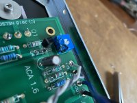
It very much looks as if you have Q3 and Q4 mixed up.
Well spotted 🙂
Yes great eye! I do have those mixed up. I do not have a solder sucker so can't correct this and see if it fixes the issue unless someone knows how to make a solder sucker.
Thanks
jh
So we await... I don't want to put a dampener on anything but I can't see how those can pull R7 down. There is no low enough impedance path to do that.
I do have another theory but that will have to wait until its all built up correctly and which is actually related to how you are measuring the voltages.
One step at a time 🙂
Yes great eye! I do have those mixed up. I do not have a solder sucker so can't correct this and see if it fixes the issue unless someone knows how to make a solder sucker.
Thanks
jh
This thread could give you ideas: Cool trick from de-soldering.
Me, when I have to desolder multilegged stuff (trimpots, caps etc.) I do it in steps, heating up one leg, remove it a bit (as much as possible without getting herculian), go to the next, etc.
Often, a „via“ (the hole in the pcb 😉 ) stays full of solder, which makes it difficult to reuse, the get the solder out, I use some resistors legs (which I put aside after cutting them)—heat up the solder in the via, put the leg in, heat the leg and pull it through. Repeat until the via is free enough to be repopulated…
Edit: have to make a mistake to test ZM‘s geaphite method 😀
Last edited:
ACA no sound
So I got the first three switched before I bent the middle leg of one of the JFETs. So close but will let you know after I get DIY to send me more parts.
Thanks
jh
So I got the first three switched before I bent the middle leg of one of the JFETs. So close but will let you know after I get DIY to send me more parts.
Thanks
jh
Is the leg long enough to solder it back on?
If it's just so-so, why not try it, sad but true if it's lost, it would have been lost if you didn't try...
If it's just so-so, why not try it, sad but true if it's lost, it would have been lost if you didn't try...
A solder sucker is the best $15 you’ll ever spend in this hobby.
Amen! Get the name brand model, Edsyn Soldapult, because its tip is vastly more heat resistant than the cheap knock offs. Also because its piston & vacuum chamber is easier to clean out (solder that it sucked for you) than cheap knock offs.
Additionally, get copper desoldering braid, ideally in two or three different widths. I prefer Techspray PROWICK but even the cheap craaap from eBay does an okay job. Dip the cheap stuff in liquid flux before using.
[emoji378][emoji90][emoji83]
Now I feel guilty of giving bad advice!
(Please listen to mooly, zm and 6l6 (edit: and mark) first, next time)
Now I feel guilty of giving bad advice!
(Please listen to mooly, zm and 6l6 (edit: and mark) first, next time)
ACA no sound
Don't be it is great advice and would have worked but I bent it getting it out of the wrong place not on the instillation. I am not sure how far down into the board the legs got but they are securely stuck in the solder on the board so I suspect it will work. Waiting for email from DIY so I can order the parts.
Do you think I cooked the bias controller (sorry for the lack of the correct name)
jh
The trimpot… it sure took a hit!
Not sure if this works on an installed pot, but try measuring from the backside (one point being the center, the other is either ground or signal, adding the values returns the pot‘s total resistance)—but resistors soldered in a circuit are often difficult/impossible to measure…
The masters know!
Not sure if this works on an installed pot, but try measuring from the backside (one point being the center, the other is either ground or signal, adding the values returns the pot‘s total resistance)—but resistors soldered in a circuit are often difficult/impossible to measure…
The masters know!
@johnah5
Fill in the location for your user profile…6L6 will fly his airplane over to help you. But seriously, there could be someone in your area willingly to help.
Fill in the location for your user profile…6L6 will fly his airplane over to help you. But seriously, there could be someone in your area willingly to help.
So conventional “Balanced Mode” is selected by having the rear switch on the ACA set to Stereo/Balanced. Then a balanced mono channel preamp signal (two signals out of phase) should be connected into the XLR input or one side of the balanced signal into one RCA and the other side of the balanced signal into the other RCA, convertí g a stereo ACA to a balanced Monoblock. This approach eliminates a large amount of second order distortion so creates a more analytical sound than a 2 channel ACA or other options.
But most people don’t have preamps with balanced output. The “Bridged Mode” only requires one unbalanced input (one channel of an unbalanced preamp into the correct RCA connector) and the back panel switch set to “Bridged Mode”. Since you need an out-of-phase signal to go along with the unbalanced input, to create balanced amp output, this is produced by the switch tapping the output of the opposite speaker post, (because it’s an inverting amp, it is out of phase), and running that strong signal through a resistor to lower it to signal level, and using that signal to create the out-of-phase leg of a balanced amp output. So since half of the balanced output has traveled through the output stage of the amp already it will have bit more, and a bit different distortion than the leg that has come directly from the RCA input. So when the two legs are combined it creates a mix. It’s darned hard to figure out what sound that slight mix should create but probably more 2nd order distortion than true balanced input from a preamp, but different than the sound of a 2 channel single chassis ACA. I think that when people talk about “balanced mode” they are usually talking about “bridged mode” not about using a balanced signal from a balanced preamp, but it isn’t clear. So there are 3 monoblock options if you have access to a balanced preamp.
But most people don’t have preamps with balanced output. The “Bridged Mode” only requires one unbalanced input (one channel of an unbalanced preamp into the correct RCA connector) and the back panel switch set to “Bridged Mode”. Since you need an out-of-phase signal to go along with the unbalanced input, to create balanced amp output, this is produced by the switch tapping the output of the opposite speaker post, (because it’s an inverting amp, it is out of phase), and running that strong signal through a resistor to lower it to signal level, and using that signal to create the out-of-phase leg of a balanced amp output. So since half of the balanced output has traveled through the output stage of the amp already it will have bit more, and a bit different distortion than the leg that has come directly from the RCA input. So when the two legs are combined it creates a mix. It’s darned hard to figure out what sound that slight mix should create but probably more 2nd order distortion than true balanced input from a preamp, but different than the sound of a 2 channel single chassis ACA. I think that when people talk about “balanced mode” they are usually talking about “bridged mode” not about using a balanced signal from a balanced preamp, but it isn’t clear. So there are 3 monoblock options if you have access to a balanced preamp.
…..What do you mean by "bridged"? Balanced mode? If so, this will provide a larger voltage swing but result in a larger output impedance. So more gain but less control. The bass may sound boomier.
I very much liked the spookiness of the ACAs in balanced mode but with the ported parallel driver design of the speakers I'm using, the bass was way too pronounced and very ill-defined. Not sure what speakers you're using but unless they present a highly capacitive load (like an ESL) the ACAs should operate with no harm to them.
The balanced mode of the ACAs gave me enough taste to go down the rabbit hole of attempting to build up some 1st Watt clones that can operate with authority in balanced mode. I liked the balanced ACA monoblocks that much.
Last edited:
assuming you soldered in all the parts correctly, then once you power up, you should be able to set the 1/2 b+ at the +side of the output capacitor via the only trimpot on the board....
so if unable to do this, then look for incorrect parts values and/or orientations and correct them...
this is all there is to it...
of the 70+ boards we did, there was only to occasions for error which were easy to correct...
so if unable to do this, then look for incorrect parts values and/or orientations and correct them...
this is all there is to it...
of the 70+ boards we did, there was only to occasions for error which were easy to correct...
No it broke at the junction metal to plastic of whatever the housing is. I know I have three back in there.
Does this need to be replaced?
We've all done that or similar at some time 🙂 I used to melt transistors and caps doing that 😱
Electrically it is probably fine. The damage looks more cosmetic than anything.
This could be a good opportunity to try and get to the bottom of the weird voltage readings on R7. It would also let you test the preset in circuit.
With Q3 and Q4 removed you remove the ability of Q1 to turn on, although it would briefly conduct as the 1000uF cap C2 charges.
So with Q3 and Q4 removed and by adding one link to short out the outer two pins of Q1 you make the amp safe to switch on.
In that state you should be able to measure:
1/ 24 volts on both sides of R7. This voltage should also be on the gate of Q2. This is the weird reading we have to resolve.
2/ About 19 volts on Q2 Source. This shows Q2 is on and conducting.
3/ About 19 volts on Q1 Drain. This FET should be off with the shorting link in place.
4/ The voltage on R10 should adjust smoothly with the preset and go from zero volts at one end all the way to 19 volts at the other. Reset it back to the middle point if you try this.
I see I missed a vital word out of post #10702
Should have read So no obvious path to ground...
Apologies for that.
So obvious path to ground. Hmm...
Should have read So no obvious path to ground...
Apologies for that.
So conventional “Balanced Mode” is selected by having the rear switch on the ACA set to Stereo/Balanced. Then a balanced mono channel preamp signal (two signals out of phase) should be connected into the XLR input or one side of the balanced signal into one RCA and the other side of the balanced signal into the other RCA, convertí g a stereo ACA to a balanced Monoblock. This approach eliminates a large amount of second order distortion so creates a more analytical sound than a 2 channel ACA or other options.
But most people don’t have preamps with balanced output. The “Bridged Mode” only requires one unbalanced input (one channel of an unbalanced preamp into the correct RCA connector) and the back panel switch set to “Bridged Mode”. Since you need an out-of-phase signal to go along with the unbalanced input, to create balanced amp output, this is produced by the switch tapping the output of the opposite speaker post, (because it’s an inverting amp, it is out of phase), and running that strong signal through a resistor to lower it to signal level, and using that signal to create the out-of-phase leg of a balanced amp output. So since half of the balanced output has traveled through the output stage of the amp already it will have bit more, and a bit different distortion than the leg that has come directly from the RCA input. So when the two legs are combined it creates a mix. It’s darned hard to figure out what sound that slight mix should create but probably more 2nd order distortion than true balanced input from a preamp, but different than the sound of a 2 channel single chassis ACA. I think that when people talk about “balanced mode” they are usually talking about “bridged mode” not about using a balanced signal from a balanced preamp, but it isn’t clear. So there are 3 monoblock options if you have access to a balanced preamp.
A great explanation, thank you. I ran mine in this mode the other day, flipping the switch back and forth from stereo to bridged mono mode, and noticed it got louder and better sounding in bridged mono. I guess I was puzzled to get any sound at all out of stereo mode considering speaker positive was hooked up to A- and speaker negative to B-.
So conventional “Balanced Mode” is selected by having the rear switch on the ACA set to Stereo/Balanced. Then a balanced mono...
But most people don’t have preamps with balanced output. The “Bridged Mode” only requires one unbalanced input (one channel of an unbalanced preamp into the correct RCA connector) and the back panel switch set to “Bridged Mode”. Since you need an out-of-phase signal to go along with the unbalanced input, to create balanced amp output, this is produced by the switch tapping the output of the opposite speaker post, ...
Perfect! Thank you for the explanation. I took a stare at the wiring diagram and was attempting to work out the bridged mode. I have a DAC with balanced outputs that I've been using so was getting confused. Clarity!
In what way does the ACA sound differ from bridged (unbalanced) to balanced. I have XLR on Cambridge DAC magic plus. But no XLR cables so never tried. Thinking hard about getting Naim Uniti Atom headphone amp and using it as music streamer DAC and pre-amp for ACA. Previous Nativ streamer is bricked.
- Home
- Amplifiers
- Pass Labs
- Amp Camp Amp - ACA