....24V x 1.5A = 36W heat dissipation per channel,
that is a lot of heat.
you need big heatsinks .
( the original ampcamp has a 19V supply)
that is a lot of heat.
you need big heatsinks .
( the original ampcamp has a 19V supply)
yes...you are right...with my 0,65K/W heat sink ...too small. i wonder if the new amp camp kits are bigger. as i looked on the store its a 2U disippante...not large...
my plan for the power supply was to use a LM350 for the rail after the SMPS and then i get about 20-22V for the amp. but as i see now. LM350 is 5V drop
VIN − VOUT = 5V....hmm... i have to think about that.
heat etc...power...
good night
my plan for the power supply was to use a LM350 for the rail after the SMPS and then i get about 20-22V for the amp. but as i see now. LM350 is 5V drop
VIN − VOUT = 5V....hmm... i have to think about that.
heat etc...power...
good night
I want to use this chassis: originaly i planned other things but the size fits for ACA.
Douk Audio DIY Aluminum Enclosure DAC Case Cabinet Amplifier Chassis New (W211*H90*D257mm)|amplifier chassis|dac caseaudio diy - AliExpress
its a bit deeper and higher but the fins are not so big. i tried in the morning this heat sink with 19V or 22V and it gets too hot with R15 2k2. i got 1,57Amps and with 19V with no load o got 67° on the Q1, Q2 IRFP240.
so how can i set the current down lets say 1,2A or so. how is this to calculate?
my SMPS (LRS150-24) can be set to 20,57V minimum --> i would use 2 fat diodes to burn about 1,4 Volts.----but that is still too much with 1,57A.
thanks
chris
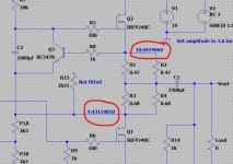
The current is set by the operating point of Q3. When sufficient voltage is developed between the base and emitter (so about 600 to 700mv) the transistor turns on and limits the current.
What current do you get with R15 removed?
What current do you get with R15 removed?
Here there is approx 600mv between B and E and the current limits at just over 1 amp
Increasing the value of the 0.47 and 0.68 ohm resistors would develop more volt drop and so allow even lower currents.
R15 and R8 simply form a divider across this already low voltage and allow setting of the current to values higher than the default of no R15 fitted.
So if you can't go low enough with R15 removed then you need to increase the 0.47 and 0.68 ohms a little, say to 0.68 and 0.82 ohm.
Attachments
The current is set by the operating point of Q3. When sufficient voltage is developed between the base and emitter (so about 600 to 700mv) the transistor turns on and limits the current.
What current do you get with R15 removed?
its about 1,07A as I wrote post before.
I want to use this chassis: originaly i planned other things but the size fits for ACA.
Douk Audio DIY Aluminum Enclosure DAC Case Cabinet Amplifier Chassis New (W211*H90*D257mm)|amplifier chassis|dac caseaudio diy - AliExpress
its a bit deeper and higher but the fins are not so big. i tried in the morning this heat sink with 19V or 22V and it gets too hot with R15 2k2. i got 1,57Amps and with 19V with no load o got 67° on the Q1, Q2 IRFP240.
I use that chassis for my ACA builds.
It is fine with 24 volts and 1,5 A standing current. I even have the SMPS mounted inside on one.
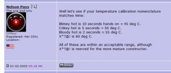
ACAs do run very hot, 55 - 65 degrees C at the heatsinks. Perhaps you do not need to worry too much?
Attachments
its about 1,07A as I wrote post before.
And you want around 1.2A?
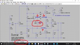
Something around 8k2 for R15 should achieve that but what you could do is fit a preset and tweak to get exactly what you want, then remove and measure and fit a fixed value in its place.
It is not an exact science to calculate because we do not know exactly what Vbe voltage your Q3 needs but we can come pretty close.
Assume 600 millivolts for Vbe.
The combined effective value of all those series and parallel 0.47 and 0.68 ohms is 0.565 ohms.
A current of 1.2 A would develop V=I*R which is 1.2*0.565 giving 0.678 volts.
We need 600 millivolts and so we need a divider across that combined resistor chain of......
We ignore the base current as it is tiny...
We know R8 = 1k and so we must 'loose' 78 millivolts across R8
That is 0.678V - 0.6V (the voltage across the resistors minus our wanted 600 millivolts)
The current in R8 will be I=V/R so 0.078/1000 which is 0.078 milliamps or 78 microamps.
We know that the remainder of the voltage will have to be developed across R15 which is the value we now calculate.
R=V/I which gives 0.6/78E-6 giving 7692 ohms.
Lets try that in the simulation and see what we get... and its pretty close. It is the voltage Vbe of Q3 that is open to variation in the calculation.
Attachments
I use that chassis for my ACA builds.
It is fine with 24 volts and 1,5 A standing current. I even have the SMPS mounted inside on one.
ACAs do run very hot, 55 - 65 degrees C at the heatsinks. Perhaps you do not need to worry too much?
Thank you Alan
I will see if the construction is ready...i am still working on it. without thread cutter this heat sinks are ugly to drill a hole and fix it with a nut🙄
And you want around 1.2A?
Something around 8k2 for R15 should achieve that but what you could do is fit a preset and tweak to get exactly what you want, then remove and measure and fit a fixed value in its place.
It is not an exact science to calculate because we do not know exactly what Vbe voltage your Q3 needs but we can come pretty close.
Assume 600 millivolts for Vbe.
The combined effective value of all those series and parallel 0.47 and 0.68 ohms is 0.565 ohms.
A current of 1.2 A would develop V=I*R which is 1.2*0.565 giving 0.678 volts.
We need 600 millivolts and so we need a divider across that combined resistor chain of......
We ignore the base current as it is tiny...
We know R8 = 1k and so we must 'loose' 78 millivolts across R8
That is 0.678V - 0.6V (the voltage across the resistors minus our wanted 600 millivolts)
The current in R8 will be I=V/R so 0.078/1000 which is 0.078 milliamps or 78 microamps.
We know that the remainder of the voltage will have to be developed across R15 which is the value we now calculate.
R=V/I which gives 0.6/78E-6 giving 7692 ohms.
Lets try that in the simulation and see what we get... and its pretty close. It is the voltage Vbe of Q3 that is open to variation in the calculation.
WOW...thats great !
Thank you Mooly
but lets check if my final metal construction could handle the heat.
i looked at the modushop and there is written that the heat sink are rated at 0,67K7W...so nearly the same as i had. this fisher heat sink is about 80g lighter then my heat sinks now.
if i push 1 Vrms input i get about 3,7Watt @4R and the FETS get "Colder" 😀53° , current goes to the load...fine for the Q2, Q2🙂....so i think during listening its not a problem...
Pleased it helped 🙂
Heat is very subjective and the FET's will be happy at temperatures far above what your fingers will take.
A very good rule of thumb is that if the actual leads coming out the FET will sizzle a drop of water then imo it really is running to hot for comfort but even that is well within acceptable limits.
It is true the amp runs cooler the harder you push it but for normal music and its average value being low I suspect that will not make a huge difference 😉
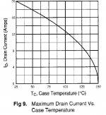
This is from a data sheet and shows allowable current vs temperature for the FET's.
Heat is very subjective and the FET's will be happy at temperatures far above what your fingers will take.
A very good rule of thumb is that if the actual leads coming out the FET will sizzle a drop of water then imo it really is running to hot for comfort but even that is well within acceptable limits.
It is true the amp runs cooler the harder you push it but for normal music and its average value being low I suspect that will not make a huge difference 😉
This is from a data sheet and shows allowable current vs temperature for the FET's.
Attachments
...enough for today...
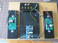
Here are some pics from my today's work
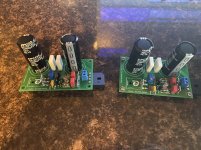
new pcb mounted to housing heat sink
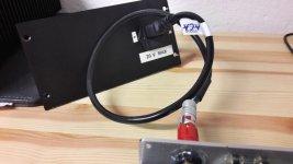
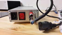
smps + connection to amp + power cable
upper and lower plate drilling 🙂
protection diode and 2 diode for voltage wasting...i will see if i need them or not
good night
6 o´clock is my morning alarm...😉
chris
Here are some pics from my today's work
new pcb mounted to housing heat sink
smps + connection to amp + power cable
upper and lower plate drilling 🙂
protection diode and 2 diode for voltage wasting...i will see if i need them or not
good night
6 o´clock is my morning alarm...😉
chris
Attachments
-
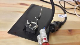 diode protection and waste of voltage.jpg78.9 KB · Views: 164
 -
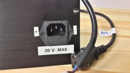 amp power cord_2.jpg73.1 KB · Views: 155
 -
 amp power cord_1.jpg72.3 KB · Views: 157
 -
 drilling air flow.jpg115 KB · Views: 164
 -
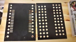 drilling air flow top and buttom.jpg108.9 KB · Views: 338
 -
 SMPS LRS150_24_2.jpg80.4 KB · Views: 352
 -
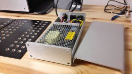 SMPS LRS150_24_1.jpg102.7 KB · Views: 358
 -
 aca glone pcb on heatsink.jpg94.2 KB · Views: 362
Looking good 🙂
I'm not convinced on the diodes tbh. Here's why...
Lets say you have 1.2A flowing and the FET's are biased to the midpoint (the midpoint exact value doesn't matter, it just makes the calculation easer. The total dissipation of the output pair is the same whether set at 9v, 3v or 15v)
So 9v @ 1.2A is 11.4 watt per device. Total 22.8 watt.
Now with the supply at 17.5 volt (two diode drops less) and with the current the same we get 10.5 watt per device, total 21 watt. Very little difference. Also the diodes now dissipate that 'lost' heat, all you have done is change the location of the heat generated.
You can achieve the same reduction by reducing the standing current and yet keep the full available voltage swing. Only when the load impedance of the speaker happens to be low and the swing high would you see limiting occur that bit earlier due to the lower current.
Remember that most speakers have their impedance way over the nominal 4 or 8 ohm value for much of the mid and upper frequencies and so would draw less current there in any case.
It is looking good though
Good morning Mooly
Yes its clear for me. my conclusion is that up to now its not clear about the total heat dissipation at the FET´s in my amp housing nor with 19Vneither at 24V. the smps what i planned (same as allan use it) has fixed 24V. that is the reason i use my LRS150-24 smps because i can trim it a bit. result is just 20,54V. with diodes i get about 19V and 1,57A so its about 30Watt.
From reading Class A amps i learned that this amps are "better" with much more current, or lets say as higher as possible (heat ) is in a acceptable area. (not over 70-75° per FET).
so lets see which heat behavior i will have in my housing.🙂
chris
Here is the difference to gain each makes with a 39k2, 43k, 56k and a 68.1k
(the dotted line is phase)
Hi Mooly
maybe this gain setting is an idea for the next ACA version😉😀 . I know that the V1.8 is the very latest one but with a nice "gain" knob it could be and idea...
Morning 🙂
Switchable gain is do-able if you really need it. You do though always have the added problem of introducing the risk of noise pickup from any wires to and from a switch.
If you are designing a PCB then you could include relay switching to select gain with each lower gain setting being achieved by switching another resistor in parallel with the existing higher value one. That way there are no problems with the switch breaking before making and the amplifier doing bad things to the speakers as the feedback loop momentarily breaks.
I can't really advise on the heat other than to say it will run at very hot temperatures quite safely. You will have to see how it all feels in your chosen case and also allow for running at higher ambient summer temperatures.
(rather than a gain switch why not have an adjustable bias current)
Hi
Thanks for your clear words to guide me here.😉
Yes you are right. it makes more sense to think about an adjustable bias if any modification are needed.
Thanks for your clear words to guide me here.😉
Yes you are right. it makes more sense to think about an adjustable bias if any modification are needed.
Hoping to get some feedback on building a large external power supply to power two amp camps (4 total boards). I plan to use:
- Pesantue 2u chassis
- 4 of Jason Keutemann’s CapMX Power supply boards (one for each channel)
- 2 AS-2222 transformers
- each amp will have it’s own umbilical cord with 3 pin input
- ground will be shared for each amp and each board will receive its own 25-27V power (voltage sags on the CapMX quite a bit).
I’ve built all in one amps with the CapMX power supply boards and transformers with the amp camps but wanting to try a separate power supply.
Are there any tips or foreseen problems I may have building a large external chassis like this?
I attached a pic of two of the power supplies.
Attachments
- Home
- Amplifiers
- Pass Labs
- Amp Camp Amp - ACA