Good question.
So, you're going going to actively crossover the RP600s to play only above a certain frequency? How?
A bit of a tongue in cheek question... not intended to be snarky, but give it some thought.
So, you're going going to actively crossover the RP600s to play only above a certain frequency? How?
A bit of a tongue in cheek question... not intended to be snarky, but give it some thought.
RE: subs...
I personally run my subwoofer off of one of the analogue outputs on my pre-amp.
My MiniDSP pre-amp allows me to configure a crossover for each output, so I send everything below 80 htz to the sub, and everything above that to the ACA. Sounds great.
Most pre-amps should have multiple pairs of analogue outputs.
Your sub should have a selectable crossover.
The system will sound better if you can activity use a crossover to the RP600’’s also. Otherwise it will be hard to integrate the sound of the subs and rp600’s without bloating the lower frequencies.
KMF
Great advice, but REL specifically designs and markets their subs to use the high level inputs. Something about retaining the natural sound of the amplifier feeding your main speakers etc. etc. Horses for courses, but I assumed that's why they were asking how to wire it directly to the ACAs.
So many options to try out.
Note: I'm surprised no one has corrected me yet. I was incorrect earlier. With the phase inversion of the ACA, the "non-inverted" signal will be from Black Terminal "A" not "B".
So many options to try out.
Note: I'm surprised no one has corrected me yet. I was incorrect earlier. With the phase inversion of the ACA, the "non-inverted" signal will be from Black Terminal "A" not "B".
need help for my first Class A ACA glone
Hi
i get infected by the Class A virus. 🙂
before i go ahead i try the glone pcb by zerozone: the same as Alan4411 in post 7134. i luckly found.
https://www.diyaudio.com/forums/pass-labs/215392-amp-camp-amp-aca-714.html#post5699938
i checked the layout against the ACA 1.1 and it looks ok. so i check all parts and the rest what rhey not deliver correct i used from my boxes. up to now i do not find this strange diode in the schematic.
the amp is up since 24 hours and powered over my lab supply with 19V. CC max to 1,5 amps.
idle current of 1 amp is 1,06A.
i set the amp to 10,06V and the Q1 gets about 60°C and Q2 is a bit hotter with 66°C. i use a 0,65K/W heat sink. room is about 23°C. strange for me because i guess that i get a better cooling but i us this glimmer pads...maybe this are not so nice....right? the amp is stable since 26 hours. nice.
instead of having the ZXT451 i got a BC550C
instead of the k246 i got a K30A
i read the first 100page 😱....and I found in post 571 the confirmation that BC550C,B, A is ok there.
Gain:
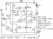
i am confused because its written in the document of ACA that the amp has a voltage gain of 14db and get out 5W.
with no load i get 24db at 1khz and 20dB gain at 30khz.
so i use a 8R resistive load and checked again. gain is 7,5 so about 17dB.
with 4R i get 4,5gain and about 13dB.
is that ok???
Power:
i do not get out more then 1W.
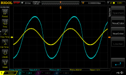
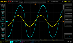
as you can see at the scope (differential probe+ Rigol 1054)
pic 1
19Vsupply_set at 10V 8R load 1khz sine in 360mVrms_out 0,8 Watt
above this i got clipping on the top...but i should go near 8Vpeak!!?
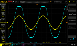
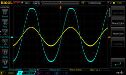
pic 2
19Vsupply_set at 10V 8R load 10khz sine in 360mVrms_out distorted
pic 3
clipping
19Vsupply_set at 10V 8R load 1khz sine in 500mVrms_out clipping
please can somebody clear this things ?
thanks
chris
Hi
i get infected by the Class A virus. 🙂
before i go ahead i try the glone pcb by zerozone: the same as Alan4411 in post 7134. i luckly found.
https://www.diyaudio.com/forums/pass-labs/215392-amp-camp-amp-aca-714.html#post5699938
i checked the layout against the ACA 1.1 and it looks ok. so i check all parts and the rest what rhey not deliver correct i used from my boxes. up to now i do not find this strange diode in the schematic.
the amp is up since 24 hours and powered over my lab supply with 19V. CC max to 1,5 amps.
idle current of 1 amp is 1,06A.
i set the amp to 10,06V and the Q1 gets about 60°C and Q2 is a bit hotter with 66°C. i use a 0,65K/W heat sink. room is about 23°C. strange for me because i guess that i get a better cooling but i us this glimmer pads...maybe this are not so nice....right? the amp is stable since 26 hours. nice.
instead of having the ZXT451 i got a BC550C
instead of the k246 i got a K30A
i read the first 100page 😱....and I found in post 571 the confirmation that BC550C,B, A is ok there.
Gain:
i am confused because its written in the document of ACA that the amp has a voltage gain of 14db and get out 5W.
with no load i get 24db at 1khz and 20dB gain at 30khz.
so i use a 8R resistive load and checked again. gain is 7,5 so about 17dB.
with 4R i get 4,5gain and about 13dB.
is that ok???
Power:
i do not get out more then 1W.
as you can see at the scope (differential probe+ Rigol 1054)
pic 1
19Vsupply_set at 10V 8R load 1khz sine in 360mVrms_out 0,8 Watt
above this i got clipping on the top...but i should go near 8Vpeak!!?
pic 2
19Vsupply_set at 10V 8R load 10khz sine in 360mVrms_out distorted
pic 3
clipping
19Vsupply_set at 10V 8R load 1khz sine in 500mVrms_out clipping
please can somebody clear this things ?
thanks
chris
Attachments

Last edited:
The gain (the voltage you see across the speaker terminals) should not alter very much as you connect an 8 ohm load. It will drop perhaps 0.5 volt or so.
It sounds like you have either a construction error (or board error) or a fault.
The bias current should be a bit higher than 1 amp but that in itself would not cause the odd results you are getting.
DC offset will always be near zero because of the AC coupling.
It sounds like you have either a construction error (or board error) or a fault.
The bias current should be a bit higher than 1 amp but that in itself would not cause the odd results you are getting.
DC offset will always be near zero because of the AC coupling.
chermann - You have the PSU set to 10V. How do you think you can get more than 1W?
Please set PSU to 19V
Also remember that ACA is positive ground, so you have to attach scope probe to speaker black and ground clip to speaker red.
Please set PSU to 19V
Also remember that ACA is positive ground, so you have to attach scope probe to speaker black and ground clip to speaker red.
Last edited:
chermann - You have the PSU set to 10V. How do you think you can get more than 1W?
Please set PSU to 19V
Also remember that ACA is positive ground, so you have to attach scope probe to speaker black and ground clip to speaker red.
........idle current should be 1,5A.
have you built this one?
hi MJF
thanks for your help.
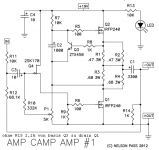
no the zerozone glone use the amp camp ACA v1.0
the feedback resistor is 68,1k. other parts are similar.
chermann - You have the PSU set to 10V. How do you think you can get more than 1W?
Please set PSU to 19V
Also remember that ACA is positive ground, so you have to attach scope probe to speaker black and ground clip to speaker red.
Hi 6L6
thanks for your reply.
sorry but..nope.
i have my power supply set at 19V and the point where the C1 + is I set to 10.06V.
i use a differential probe since i do some measurements with class D.
chris
Last edited:
The gain (the voltage you see across the speaker terminals) should not alter very much as you connect an 8 ohm load. It will drop perhaps 0.5 volt or so.
It sounds like you have either a construction error (or board error) or a fault.
The bias current should be a bit higher than 1 amp but that in itself would not cause the odd results you are getting.
DC offset will always be near zero because of the AC coupling.
Hi Mooly,
thanks for you, reply.
here are the measurements i took yesterday after set up. first i tried to set about 12V with 9V supply. then i cheked with 24V supply but my IRFP240 get very hot = 80°C.
so i decided to keep 19V first and then go up if everything is sane.
chris
Attachments
...i found the failure..
sorry but i lend my scope and my probe (differential probe) and i dont check the settings. now its corrected because my diff probe has to be set 20X at the scope...i am a dummy...🙄
never the less i got "just" 3W - 15Vpp. so the amp eats about 4V.
i use at 10khz 420vrms input and at at 1khz its getting clipping
chris
Attachments
.....but now we know what schematic you used.
afaik the ampcamp is made for 8 ohm loads............
a bias of only 1A (instead of 1,5A) lowers the output power significantly.......
what source (frequency generator ?) , what is the output impedance
of this source?
afaik the ampcamp is made for 8 ohm loads............
a bias of only 1A (instead of 1,5A) lowers the output power significantly.......
what source (frequency generator ?) , what is the output impedance
of this source?
You say "I found the failure".
Are you saying it is sorted?
Your scope shots show a problem with gain. If you have the ACA built as mjf's diagram then 420mv rms at the input should give about 2.2 volts rms at the output. It will vary a little depending on the load impedance such as 8 ohm or no load.
So your scope shot of 420mv in and around 5.5 or 5.6 vrms out shows a problem with the gain which suggests a problem with the feedback resistor values. You mentioned using the 68.1k feedback resistor.
I wonder if the transconductance of that 2SK30A FET is also causing an issue.... but higher gain, that doesn't compute.
Hi Mooly,
no nothing is solved. just the power is better....but thats not the issue.
yes you are right. the gain is too high. that is cause i start to ask here ...
yes i use the 68,1k resistor.
i check the voltage values during running amp and no signal, of course with 8R.
and give the results
chris
no nothing is solved. just the power is better....but thats not the issue.
yes you are right. the gain is too high. that is cause i start to ask here ...
yes i use the 68,1k resistor.
i check the voltage values during running amp and no signal, of course with 8R.
and give the results
chris
.....but now we know what schematic you used.
afaik the ampcamp is made for 8 ohm loads............
a bias of only 1A (instead of 1,5A) lowers the output power significantly.......
what source (frequency generator ?) , what is the output impedance
of this source?
i use a rigol DG1022 its about Z= 50R channel 1
data sheet:
Kanal 1:
2 mVpp ~ 10 Vpp (50 Ω)
4 mVpp ~ 20 Vpp (high imp.)
thank you for your help
So my values for the part i used:
measured value - schematic value
R11 9k98 input - 10k
R12 67k8 - 68k1
R10 330k -332k
R5,R6 99,5R -100
R7,10k12-10k
R13 is not existing at the glone pcb
C4 is not existing at the glone pcb
R8, R9, 1k2 - 1k - false ?
R14 Bleeder resistor -Thump avoid 1k5 -1k
R1,R2, R3, R4 are as recommended measured with my LCR meter at 10khz
C2 1800µF/25V - 1000µF
C3 is a nichicon muse black UKZ 10µF
C1 i use a 5600µF/16V nichicon with 100µF Silmic 2 and a 47µF nicihon FW🙄😀
..measure during power...load 8R no signal
Hi
between chrsitmas preparation🙂 i try my best according to post 922
https://www.diyaudio.com/forums/pass-labs/215392-amp-camp-amp-aca-93.html#post3471735
19V supply over lab supply, CC is set to 1,9A
power up was idle current 1,16 goes down to 1,07A
working point for this amp should be 10V its going from 10,17 during switch on down to 10,06V
then i measured all values:
Q4 gate 4,68V
Q2 Gate 14,85V
Q2 D 18,97 = 19V supply ok
Q2 S 10,33V
Q2 S 10,33V
Q1 G 4,55V
Q1 D 9,69V
Q1 S 3,1mV
Voltage at R1,R2 (47mohm) = 0,265V
Voltage at R3,R4 (68mohm) = 0,371V
C2 voltage is 5,12V its the point between the R5 (not the gate side) and the lower part of R3,R4 (0,68R) resistor or Q1 Drain
Q1 and Q2 Gate to Drain 4,51V
Q3 BC 550C Base Emitter 0,629V
temp of Q2 is 65° C, Q1 61°C
Last edited:
- Home
- Amplifiers
- Pass Labs
- Amp Camp Amp - ACA