so the statement at the post 922 is wrong? 2nd last sentence
Measure the voltage from Emitter to Collector of Q3 (or across C2). It should be about 5V
Measure the voltage from Emitter to Collector of Q3 (or across C2). It should be about 5V
5 volts across the cap sounds right.
My fault, it was the way it was written and the 'not the gate side' had me thinking you were measuring from the other side of the cap.
My fault, it was the way it was written and the 'not the gate side' had me thinking you were measuring from the other side of the cap.
Out of interest, does your PSU have a connection to mains earth? If so does your scope / signal generator also have a connection to mains earth?
Hi Alan
yes all my lab things are earth grounded.
i use a lab supply DP832 and i use no earth outlet (green) just between red and black 19V
frequency generator is DG1022.
rigol 1054
chris
yes all my lab things are earth grounded.
i use a lab supply DP832 and i use no earth outlet (green) just between red and black 19V
frequency generator is DG1022.
rigol 1054
chris
Reason I asked was there have been several posts where the OP has 'shorted' the output of the ACA testing it. ACA (Meanwell ) PSU is earthed. Giving low power and clipping.
The OP forgets that the Red output terminals are GND / 0 volts. Then uses the ACA Black output terminals for the scope negative /ground / earth. That creates a 'short' via the earth connections.
Lifting one of the earth connections while testing cures the problem.
The OP forgets that the Red output terminals are GND / 0 volts. Then uses the ACA Black output terminals for the scope negative /ground / earth. That creates a 'short' via the earth connections.
Lifting one of the earth connections while testing cures the problem.
Last edited:
Hi Alan
yes you are right . before using scope think about what could happened.🙂
EEVblog #279 - How NOT To Blow Up Your Oscilloscope! - YouTube
your glone ACA is still running?
Do you have an idea?
chris
yes you are right . before using scope think about what could happened.🙂
EEVblog #279 - How NOT To Blow Up Your Oscilloscope! - YouTube
your glone ACA is still running?
Do you have an idea?
chris
not problem... you want to help me.... so i am happy😉🙂
This is very strange then.
Can we go back to basics and revisit post #9254 and those scope shots.
No need to post pictures but can you confirm (and this time use just one channel on the scope for both measurements) that you really are seeing around 5.5 volts rms output for just 420mv rms input.
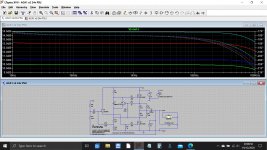
I've set that up in the simulation we have for this amp to show you what you should get. This is using the 68.1k and 10k gain set networks of the earlier version you have.
Removing the 8 ohm load should show only a very small increase in output.
Attachments
amp camp amp input sensitivity?
I will be building a pair of ACAs and I want to buy a passive preamp for them.
I need the input sensitivity for the amps please. Thanks
I will be building a pair of ACAs and I want to buy a passive preamp for them.
I need the input sensitivity for the amps please. Thanks
Sensitivity is very low at around 1.2vrms for the early version (and 19v PSU) and around 2.2vrms for the later version (and 24v PSU)
So you might be struggling a little with a purely passive setup.
So you might be struggling a little with a purely passive setup.
Don't, most people find they need 6 - 10dB of gain. Unless you have a very high output source (?) and super sensitive speakers.I will be building a pair of ACAs and I want to buy a passive preamp for them.
I need the input sensitivity for the amps please. Thanks
... your clone ACA is still running?
Do you have an idea?
chris
No, I have built proper ACAs now. Also I only used the Chinese boards. All the components were to the full v1.6 specification.
Also the version 1.0 ACA only delivers 2 watts for 1% distortion. Maybe yours sounds better than it measures? Try adding the 2.2k resistor R15?
Last edited:
...amp is working now..
Hi to all
thanks for your help but i found it...shame on me...🙄
Mooly reminds me at the bad feedback network and i looked with channel 3 after the 68k resistor and found nearly the same input signal. that made me crazy! --> finally i found my mistake. i sort after measuring the resistors in the wrong box and then i soldered it...no recheck again.🙄🙄🙄
so i used at R11 input and R7 instead of a 10k resistor a 1k resistor !!!
now the amp is working fine gain about 4,6 and the max power is about 3,75Watt with the supply 19V and the set of 10,2V.
Q1, Q2 have just 55°C so next step could be 24V.
for 24V i have to use the 2k2 as R15 ...right?
and i have to use as Rf 90.1k in parallel with a 10pF mica...right
i am really sorry to be such an idiot and ask you.
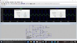
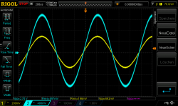
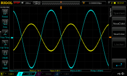
pic 1 19Vsupply_set at 10V 8R load 1khz sine in 200mVrms_gain 4,57
pic 2 max power 19Vsupply_set at 10V 8R load 1khz sine in 1320mVrms_gain 4,57_power about 3,75Watt
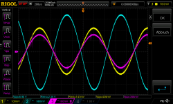
pic 3 is the 3 channel after the feedback resistor before input cap.
Thanks all for help me.
chris
Hi to all
thanks for your help but i found it...shame on me...🙄
Mooly reminds me at the bad feedback network and i looked with channel 3 after the 68k resistor and found nearly the same input signal. that made me crazy! --> finally i found my mistake. i sort after measuring the resistors in the wrong box and then i soldered it...no recheck again.🙄🙄🙄
so i used at R11 input and R7 instead of a 10k resistor a 1k resistor !!!
now the amp is working fine gain about 4,6 and the max power is about 3,75Watt with the supply 19V and the set of 10,2V.
Q1, Q2 have just 55°C so next step could be 24V.
for 24V i have to use the 2k2 as R15 ...right?
and i have to use as Rf 90.1k in parallel with a 10pF mica...right
i am really sorry to be such an idiot and ask you.
pic 1 19Vsupply_set at 10V 8R load 1khz sine in 200mVrms_gain 4,57
pic 2 max power 19Vsupply_set at 10V 8R load 1khz sine in 1320mVrms_gain 4,57_power about 3,75Watt
pic 3 is the 3 channel after the feedback resistor before input cap.
Thanks all for help me.
chris
Attachments

Last edited:
 wonderful.
Putting those values into the simulation gives your original fault 😉
You should set the midpoint volts with scope and a suitable load representative of what you will use (8 ohm etc) and adjust for symmetrical clipping.
2k21 for R15 and 24 volts.
Attachments
Feedback... I've not heard of the 90.1k and 10pF before but that would give you almost the same as the 39k2 of the later version.
These are not critical at all... you are going from 68k to 39k to decrease the gain. Just use a 39k if you feel you want to make the change to lower gain.
These are not critical at all... you are going from 68k to 39k to decrease the gain. Just use a 39k if you feel you want to make the change to lower gain.
thanks Mooly
i will re check the 2nd pcb , change to 24V, build both channels and start mounting to a mock up that i can listening soon😀
i build a fresh Scan speak luxury loudspeaker called "NADA" its 4R so i guess i have to go up to 24V and more current=bias right?
thx
i will re check the 2nd pcb , change to 24V, build both channels and start mounting to a mock up that i can listening soon😀
i build a fresh Scan speak luxury loudspeaker called "NADA" its 4R so i guess i have to go up to 24V and more current=bias right?
thx
thanks Mooly
i will re check the 2nd pcb , change to 24V, build both channels and start mounting to a mock up that i can listening soon😀
i build a fresh Scan speak luxury loudspeaker called "NADA" its 4R so i guess i have to go up to 24V and more current=bias right?
thx
That sounds like a plan 🙂
The higher supply voltage allows more voltage swing into the load and so the bias current needs to also be higher to ensure that this higher voltage can delivered across the load.
If the current is limited then the voltage can never be achieved.
If your load were say 16 ohms then we could reduce the bias and still get full output.
Hi Mooly
thanks for the LT spice simulations.
i just add this R15 on my board and checked my supply what i want to use. is a single supply with 24V but real 23,88V under load its stable with 23,87V.
here:
AC 85 265V to DC 12V 24V 6A 100W Switching Power Supply Board Power Supply Module|Switching Power Supply| - AliExpress
i tested it with some 20mF caps no hick up or other strange things during starting...
with just adding the R15 and keep the 68k Rf and 4 ohm load i get a gain of 4.
i try with max input voltage = 1,2vrms to set the point where is in the middle.
i adjust in the middle 11,94V
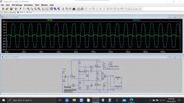
see pic1
the problem is the lab supply is set to 23,88 and it push 1,54A inside the amp and i get very fast about 76°C on each IRFP240 !!
is that too much?! do i have to use 39k at Rf?
thx
chris
thanks for the LT spice simulations.
i just add this R15 on my board and checked my supply what i want to use. is a single supply with 24V but real 23,88V under load its stable with 23,87V.
here:
AC 85 265V to DC 12V 24V 6A 100W Switching Power Supply Board Power Supply Module|Switching Power Supply| - AliExpress
i tested it with some 20mF caps no hick up or other strange things during starting...
with just adding the R15 and keep the 68k Rf and 4 ohm load i get a gain of 4.
i try with max input voltage = 1,2vrms to set the point where is in the middle.
i adjust in the middle 11,94V
see pic1
the problem is the lab supply is set to 23,88 and it push 1,54A inside the amp and i get very fast about 76°C on each IRFP240 !!
is that too much?! do i have to use 39k at Rf?
thx
chris
Attachments
- Home
- Amplifiers
- Pass Labs
- Amp Camp Amp - ACA