I’ll take a stab at it. Wasn’t sure if I would have any grounding issues with my plan or not.
..ACA is up and running...hot but...
Hi
since yesterday i am finished with the ACA glone. pictures will follow the next days. voltage is as i wrote Just 20,57V from the SPMP but the bias current is each 1,57A😱😀.
sound is nice and lay back. relax and clear...the highs are not super clear..lets say a bit rounded...not bad for some Watts🙂
because of my known 10µF nichicon UKZ input cap i need some burning in hours to can compare to my other amps.
i was active as the ebay kit LM1875😉 and more then 2 years ago i build some TPA3250 +3255 TPA3116 amps (what is wrong with TPA3255..fx502xpro)
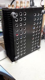
housing gets warm....chip without signal get about 68° so i guess i am on the limit with this small case. after running into 4R speaker i get just 54°
chris
Hi
since yesterday i am finished with the ACA glone. pictures will follow the next days. voltage is as i wrote Just 20,57V from the SPMP but the bias current is each 1,57A😱😀.
sound is nice and lay back. relax and clear...the highs are not super clear..lets say a bit rounded...not bad for some Watts🙂
because of my known 10µF nichicon UKZ input cap i need some burning in hours to can compare to my other amps.
i was active as the ebay kit LM1875😉 and more then 2 years ago i build some TPA3250 +3255 TPA3116 amps (what is wrong with TPA3255..fx502xpro)
housing gets warm....chip without signal get about 68° so i guess i am on the limit with this small case. after running into 4R speaker i get just 54°
chris
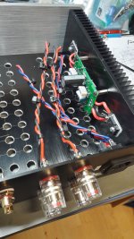
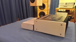
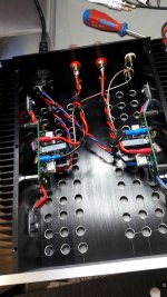
...some pics..
Merry Christmas to all !!
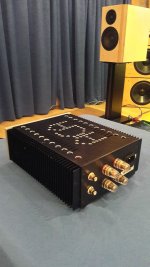
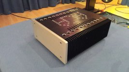
Here are some final pictures...I ám very happy with that amp.
Thanks to Nelson PASS -......... so my first PASS DIY is done.😉
open point is the supply noise -its about 180mV from the LRS150-24V...not clear for me how i can get with a laptop supply better noise value. but this is the next step...🙂
chris
Merry Christmas to all !!
Here are some final pictures...I ám very happy with that amp.
Thanks to Nelson PASS -......... so my first PASS DIY is done.😉
open point is the supply noise -its about 180mV from the LRS150-24V...not clear for me how i can get with a laptop supply better noise value. but this is the next step...🙂
chris
Attachments
-
 pre installation_no caps at supply.jpg247.4 KB · Views: 361
 -
 ACA amp_3.jpg255.9 KB · Views: 182
 -
 ACA amp_2.jpg113.8 KB · Views: 179
 -
 ACA amp_1.jpg262.8 KB · Views: 184
 -
 ACA amp_4.jpg138.6 KB · Views: 196
 -
 ACA amp_with supply.jpg98.6 KB · Views: 183
 -
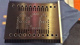
 buttom plate.jpg148.6 KB · Views: 365
 -
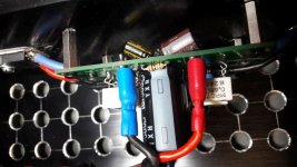 output caps.jpg73 KB · Views: 351
 -
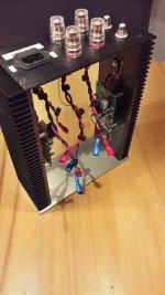 pre installation_1.jpg179 KB · Views: 361
 -
 pre installation_2.jpg215 KB · Views: 357

Beautifully done and with your own artistic touch and modifications to suit your needs. Fantastic!
And, you got a "fugly" from ZM on your first build. 😀
Merry Christmas!
And, you got a "fugly" from ZM on your first build. 😀
Merry Christmas!
Yes yes yes .....i got a fugly by mighty ZM !!!!!!!!!
the ACA letters are a bit too closed together...but at the next amp i promise it will be better 😉
the ACA letters are a bit too closed together...but at the next amp i promise it will be better 😉
open point is the supply noise -its about 180mV from the LRS150-24V...not clear for me how i can get with a laptop supply better noise value. but this is the next step...🙂
chris
Is that not less than the Meanwell 'brick' SMPS that the kit uses?
in the instruction i read:
Performance
Constructing this circuit results in a power amplifier which has 14 dB of voltage gain and 5 watts of output. The input impedance is 10 Kohm, and the damping factor is about 3.
The output noise with the switching supply comes in around 100 uV.
thats the reason why...
Performance
Constructing this circuit results in a power amplifier which has 14 dB of voltage gain and 5 watts of output. The input impedance is 10 Kohm, and the damping factor is about 3.
The output noise with the switching supply comes in around 100 uV.
thats the reason why...
Hmm... interesting.
What really counts is something called PSRR or power supply rejection ratio. That is a measure of how well (or otherwise) an amplifier rejects noise on the rails. If you look at data sheets for opamps this is usually quoted and can be 100db or more at lower frequencies.
What really counts is something called PSRR or power supply rejection ratio. That is a measure of how well (or otherwise) an amplifier rejects noise on the rails. If you look at data sheets for opamps this is usually quoted and can be 100db or more at lower frequencies.
my experience with smps is such that i am now using them on class ab amps and chip gain clones...
Merry Christmas Tony 
Yes, SMPS really suit designs like the ACA and are an integral part of the concept. I think you will find the PSRR not great on the ACA at 100/120Hz but that doesn't matter with the SMPS because the noise is more wideband being spread over a wide bandwidth.
So it all becomes a non issue with the SMPS.
 Merry Christmas Karl,
open point is the supply noise -its about 180mV from the LRS150-24V...not clear for me how i can get with a laptop supply better noise value. but this is the next step...🙂
chris
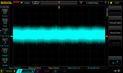
is this 180mV "peak-peak" or rms (effektiv)?
if the case is too hot, there is some place to build in an extra heatsink.
perhaps in the middle on the bottom - or so what
its 180mVpp.
heat is on the boarder i will say...with 4R and 20,3V at the amp pcb + 1,57A its really enough...
so warm up too long without signal the IRFP240 got 72° and more....so just listening😉
heat is on the boarder i will say...with 4R and 20,3V at the amp pcb + 1,57A its really enough...
so warm up too long without signal the IRFP240 got 72° and more....so just listening😉
my experience with smps is such that i am now using them on class ab amps and chip gain clones...
hi
yes at the LM1875 ebay thread Fred and others are using this 300W dual rail supply without SQ difference to non regulated psu.
....hmmm.. look at the scope pic i have done..
i am thinking about the LM350 regulator
can i measure this PSSR with scope?
chris
Attachments
You could get an idea of the PSRR using a scope,
Here is an example of PSRR using the simulation.
With no audio input supplied the output of the amp should be just its own inherent circuit noise (hiss).
If we add ripple to the rail then that should not couple into the audio chain via injection by the rails, however in practice it does.
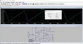
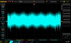
Here is the simulation for a linear type power supply producing 100Hz ripple. The voltage is nominally 24 volts DC but superimposed on that is a 100Hz sawtooth as you might see from a diode bridge and reservoir cap setup.
First image is the 250mv peak to peak ripple (145mv rms) voltage sitting on top of the 24 volt DC rail.
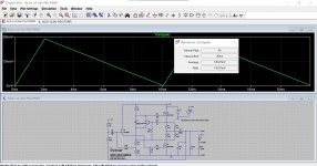
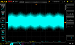
The second image is the voltage seen across the speaker. This is the ripple component making its way into the output.
The PSRR is the change in supply voltage/change in output voltage and usually quoted in db.
PSRR = 20log (VrippleIn/VRippleOut)
Here we get around 46db.
Here is an example of PSRR using the simulation.
With no audio input supplied the output of the amp should be just its own inherent circuit noise (hiss).
If we add ripple to the rail then that should not couple into the audio chain via injection by the rails, however in practice it does.
Here is the simulation for a linear type power supply producing 100Hz ripple. The voltage is nominally 24 volts DC but superimposed on that is a 100Hz sawtooth as you might see from a diode bridge and reservoir cap setup.
First image is the 250mv peak to peak ripple (145mv rms) voltage sitting on top of the 24 volt DC rail.
The second image is the voltage seen across the speaker. This is the ripple component making its way into the output.
The PSRR is the change in supply voltage/change in output voltage and usually quoted in db.
PSRR = 20log (VrippleIn/VRippleOut)
Here we get around 46db.
Attachments
...noise of regulator LM350...
Hi i build the regulator according to the schematic of figure 22. pic1
the input cap is a 2nd Denon 10000µF in parallel with a new 220nF film cap and a 10µF new 10µF rubicon.
output is a new 1µF cap.
pic 2 noise a t the input directly after my lab supply - i thought that i have a noise of 0,001 % of the Voltage . so i set the regulator to 20V output and the input was 22,50V....fine load was 2x8,2R 10W resistors. so i expect a nosie of 20mVpp...or not?
why i do not have a nice output ripple of about 20mV or so??
pic 3
chris
pic 3
Attachments
Given that the ACA draws an essentially constant current you can actually use that as your load.
There looks to be a lot of very high frequency noise on those images. Is that coming from your lab PSU? Is it a switching type? Many are.
There looks to be a lot of very high frequency noise on those images. Is that coming from your lab PSU? Is it a switching type? Many are.
Hi Mooly
thanks that you are online...😉
sorry for the late reply...Yes its the rigol DP832 and i guess its a SMPS.
the regulator is working...i can adjust with the pot the output voltage and the LM350 needs about 2,3V for itself.the ripple is not really nice to see but the saw tooth voltage is still high at the output...Why? The Chip is brand new.
chris
I've no quick answers on that but would suggest you first of all make sure the scope trace is clean (a straight line with zero noise on it) when you short probe tip and probe ground together and then assuming that is OK touch the still shorted tip to the ground you are using for the output of the regulated supply.
If you then see noise you have have a conventional layout and grounding problem. Regulators are just as critical on correct grounding as amplifiers to achieve the lowest noise and ripple.
The low frequency noise component I see is the sine wave at 50Hz and so could be a ground loop formed by the PSU and Scope and any other test equipment.
- Home
- Amplifiers
- Pass Labs
- Amp Camp Amp - ACA