Could you please elaborate into this enhancement? Where is this inserted? Diagram? Photos? Values? 🙂...but I've installed a cap multiplier inside the ACA cabinet which ramps up the power slowly. The idea behind the cap multiplier is channel separation - 100dB I believe....
Thanks a lot, best regards,
Rafa.
Could you please elaborate into this enhancement? Where is this inserted? Diagram? Photos? Values? 🙂
Hi Rafa
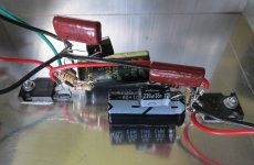
You'll find more info in the Juma's Easy-Peasy Capacitance Multiplier thread. It goes between the PSU and ACA boards, but be aware that there is a drop of 4V (needs 4V higher PSU voltage to begin with), plus quite a bit of heat from the Mosfets. I used the bottom plate of the DIY ACA chassis for mounting the IRFP240's. IRFP250's can also be used.
I have used a modified schematic for the two channels. Note that the output voltage is always 4V less than the input voltage. So, if you need 24V out, start with 28V in.
The benefits of a Cap Multiplier are:
- Reduced cross-talk between channels.
- A soft-start mechanism to slowly ramp up the current.
- It also provides a nice ripple reduction as a side benefit.
.
Attachments

Last edited:
I was thinking about the same thing, but then I checked the SMPS and realised that it is of a very high quality; the voltage drop at its output is only 2mV (!) going from idle (no current draw) to 4A constant current draw. I did not measure the ripple but my experience tells me that the ripple increase would be minimal as well. Mr Pass measured its output noise and was also quite impressed. So, I can see how the channel separation could improve, but only with a stereo ACA, where one amp handles both stereo channels, so even less of a need for this multiplier with monoblocks...
When I stressed the amp with 6ohm (resistive) load, it performed quite well with no ringing, no overshoots; I could not see any SMPS switching frequency artefacts at its output; this was, mind you, measured/observed with a 100MHz scope - I did not plot the distortion curve(s) vs. load vs. output level to check if the switching frequencies' harmonics were affecting the THD / noise.
When I stressed the amp with 6ohm (resistive) load, it performed quite well with no ringing, no overshoots; I could not see any SMPS switching frequency artefacts at its output; this was, mind you, measured/observed with a 100MHz scope - I did not plot the distortion curve(s) vs. load vs. output level to check if the switching frequencies' harmonics were affecting the THD / noise.
The ripple is documented here:
https://cdn.shopify.com/s/files/1/1006/5046/files/GST120A-spec.pdf
One can improve on it, yes. Will it sound better? We’ll have to wait and see 😉
Best,
Anand.
https://cdn.shopify.com/s/files/1/1006/5046/files/GST120A-spec.pdf
One can improve on it, yes. Will it sound better? We’ll have to wait and see 😉
Best,
Anand.
Anand,
Thanks for the explanation. I am getting mixed information it seems. I run purely bridged mode xlr and some mentioned its ok to use 4 Ohm rated speakers. I did not build with the option to run Stereo.
I am using Martin Logan Motion 40 mainly because they are the most efficient speakers I have. Specs below. What I'm, confused about are the specs, it shows as 4 Ohms but compatible with 4, 6, or 8 Ohm rated amplifiers. ?? What are your thoughts? Here is an older post with my speaker choices.
Sensitivity 92 dB/2.83 volts/meter
Impedance 4 Ohms Compatible with 4, 6, or 8 Ohm rated amplifiers.
mpitogo,
ZenMod in his f/u post is right on the money.
But what is important to find out is what your impedance curve from 20Hz to 20khz looks like. If the ML speaker dips to 4 ohms at like 20khz, nobody cares and nobody should. There is no music up there, so the amp will never be taxed. But if the dip to 4 ohms is happening in an area where there is a lot of music (ie 50Hz to 5khz), it might be of interest. And how often it dips to 4 ohms within that frequency range becomes important too (along with the phase angle).
Which is why I said without proper measurements it is impossible to give a concrete answer. This is why these types of measurements should ALWAYS be divulged by the manufacturer, so that enthusiasts can properly choose compatible amplifiers and amplifier topologies.
Best,
Anand.
Could you please elaborate into this enhancement? Where is this inserted? Diagram? Photos? Values? 🙂
Thanks a lot, best regards,
Rafa.
Hi Rafa,
I am using Cap Mx with all my projects, have been doing it for a number of years now.
Here are my simple rules, based on the parts that I have:
R5 (in Juma's diagram) is between 22 - 33k, very rarely more.
Caps 220 - 330uF (voltage depending on the requirements).
gate resistor 1k.
diode 1N4007.
Mosfet IRFZ40 or IRFZ44, because I have hundreds of them and their transconductance if very high.
Always using left over strip boards, makes for a very easy assembly.
Below are some photos.
Attachments

Not exactly 🙂
The idea is to measure the applied AC signal and the AC output level using a DVM to try and see why one of your channels is quieter than the other.
First disconnect the speaker. Now connect just one input socket to your player/preamp because we are testing each channel separately.
1/ Set the meter to AC voltage.
2/ Connect the black lead of the meter to the Red speaker socket (which is ground on the ACA)
3/ Connect the red lead of the meter to the Black speaker socket.
4/ Play the tone and adjust the volume to give a reasonable output voltage on the channel under test. The ACA should be able to easily reach 6 volts rms so aim for that.
(Absolute value is unimportant because we are only comparing readings and also seeing if the gain works out correctly)
Write the result down.
5/ Now transfer the red meter lead to the 'input' side of R11. This is the end that goes to the input wiring and sockets.
6/ Without altering the volume write down the reading you see.
Those two results give you an output voltage and corresponding input voltage. From those two results we can confirm if the board is working correctly.
8/ Without altering any settings now swap the input to the other channel and repeat the test. You should be seeing similar readings of output voltage and input voltage on R11.
Lets see where yours falls down on this.
Hi Mooly,
This is the most understood instruction you have given me. I was about to do the step by step procedure. I have just powered off the problematic amp sitting sideways with both covers off. Both boards did not produce any sound again.
When I moved the amp closer to me I heard a click or similar sound. I pushed the big capacitor, it is not really loose but I decided to put some more solder under the board. Then cut shorter the leads. I did the same to the other board, the big capacitor of which, one lead is cut and the other not.
After reinstalling the boards, I powered the amp on and heard a similar sound from my test speakers, what I always hear when powering on the other working amp. I think I felt a bit of joy. I hooked it up and there you go, beautiful sound. Listened to it for more than four hours and nothing bad happened.
So what can I say. The problem was so simple. Was that the leads touching the heatsink? I think I assumed the spacer under the board was tall enough so as not to cause for the any extended wiring or leads to touch the heatsink. I checked the working amp and found out that the capacitor leads are all shortened. Why I did not cut all excess leads in the now working amp, I forgot. But maybe rushing to finish them both.😱
So for now, I would just like to thank you for all the effort and time you spent to help me. Until you told me that you have not actually seen the amp itself I always thought you have built one before. Amazing.
I also would like to acknowledge all the other members for all their suggestions on how to fix the problem. Thanks all.
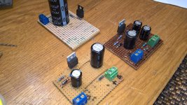
I use a LCLC PSU for each channel (picture). The chokes ensures a slow built up. I have less than 1 mV ripple at 1.4 A. It is 100% silent and the sound is very good. Each choke is a double choke so I can couple them symmetrical for better noise cancellation.
I always wanted to build one of those. But the more I read about it got way over my head. The math was just not going to happen in my life time.
So my question is there a universal LCLC PSU ? For us that want one but we are only at the level to copy what someone else provides. Like the universal power supply at diyaudiosstore. I have build one of these power supplies and was really impressed with it and felt accomplishment even though a little smoke came out the first time I turned it on.
Last edited:
I always wanted to build one of those. But the more I read about it got way over my head. The math was just not going to happen in my life time.
So my question is there a universal LCLC PSU ? For us that want one but we are only at the level to copy what someone else provides. Like the universal power supply at diyaudiosstore. I have build one of these power supplies and was really impressed with it and felt accomplishment even though a little smoke came out the first time I turned it on.
I use Duncans PSU designer II tool (free download) to design the PSU to hit the required output voltage/ripple at a given current. I went for 24VDC / 1.5A and ended up with 23.8VDC. The output voltage depends very much of the parameters of transformer and chokes. Let us say you have 2 ohm RDC in each choke in a LCLC circuit it will give 4 volt voltage drop for each A you draw. Also the "loss" in the secondary of the transformer will influence the final output voltage. But all parameters can be dialed in….in the tool. Then it can simulate both inrush curves and after inrush where it stabilizes. It also makes a difference if it is a normal bridge or schottky diodes. Usually it will be "good enough" if you can hit within 1-2 V. ACA would also work at 22VDC or 25VDC.
…...and if you use an "over dimensioned" transformer as I do it will be more or less the idle voltage of the transformer secondary that will stay stable during work load. Where I live the main is quite stable at 230 VAC but it can change and maybe drop to 220 VAC or raise to 235 VAC.
…..usually these PSU will "overshoot" a bit during inrush so good to have bleeder resistors to "eat" the energy to reduce "overshoot". Capacitors and circuit should be able to handle this. Also if you power on the PSU without any load the capacitors voltage ratings should be high enough to handle idle the voltage.
Downloading Duncans transformer tool software . If it’s easy enough that I can use it and understand it I will definitely be building one of those in reading deeper into the literature on The capacitor multiplier for in down amp ripple it states it drops the voltage about 2 V when applied to the circuit. Would it also be a good idea to install some sort of soft start circuitry to slow down to in rush?.
The more I see the more I read the more I learn. The more I learn the more questions I have and the more I realize how little I have learned and how much more there is to learn. MEPER you opened a whole new canna worms for me to get myself in trouble with ,thank You. I always like over doing and over building you can never have enough heat sinks and the power transformer can never be big enough.
The more I see the more I read the more I learn. The more I learn the more questions I have and the more I realize how little I have learned and how much more there is to learn. MEPER you opened a whole new canna worms for me to get myself in trouble with ,thank You. I always like over doing and over building you can never have enough heat sinks and the power transformer can never be big enough.
Then you have to play a bit with Duncans tool. You can add and edit RC or LC sections and edit the parameters. You can use a current generator as load etc.....lot of possibilities and there is a bit of a learning curve to learn how to use the tool. It is more difficult to design high voltage PSUs for tube amps because components has more loss. Many "tube guys" use this tool. It was recommended by some very experienced people in the DIY tube forum.
Hi Mooly,
This is the most understood instruction you have given me. I was about to do the step by step procedure. I have just powered off the problematic amp sitting sideways with both covers off. Both boards did not produce any sound again.
When I moved the amp closer to me I heard a click or similar sound. I pushed the big capacitor, it is not really loose but I decided to put some more solder under the board. Then cut shorter the leads. I did the same to the other board, the big capacitor of which, one lead is cut and the other not.
After reinstalling the boards, I powered the amp on and heard a similar sound from my test speakers, what I always hear when powering on the other working amp. I think I felt a bit of joy. I hooked it up and there you go, beautiful sound. Listened to it for more than four hours and nothing bad happened.
So what can I say. The problem was so simple. Was that the leads touching the heatsink? I think I assumed the spacer under the board was tall enough so as not to cause for the any extended wiring or leads to touch the heatsink. I checked the working amp and found out that the capacitor leads are all shortened. Why I did not cut all excess leads in the now working amp, I forgot. But maybe rushing to finish them both.😱
So for now, I would just like to thank you for all the effort and time you spent to help me. Until you told me that you have not actually seen the amp itself I always thought you have built one before. Amazing.
I also would like to acknowledge all the other members for all their suggestions on how to fix the problem. Thanks all.
Thanks for the kind words 🙂 and the main thing is that you have got your ACA working

Enjoy 🙂
Could you please elaborate into this enhancement? Where is this inserted? Diagram? Photos? Values? 🙂
Thanks a lot, best regards,
Rafa.
If interested in some explanation, see the excellent eevblog youtube channel about capacitance multipliers:
YouTube
Ok....and the heatsinks gets hot? …..about 45-50 C?
Next step would be to look at a test signal (after ensuring DC power looks good). It requires a scope to look at and a test generator and an e.g. 8 ohm power resistor as load.
The heatsinks gets warm, how warm I don't know. I will turn it on and take its temperature 🙂
So I guess the conclusion is that there either isn't anything wrong with it or something I am not qualified or able to do anything about.
Maybe I just have to high expectations?
It is probably not fair to expect this little amp to sound as good as my Hegel.
With the right speakers (and preamp) you'be surprised.
I don't think Hegel is Class-A, so apples and pears comes to mind.
The heatsinks gets warm, how warm I don't know. I will turn it on and take its temperature 🙂
So I guess the conclusion is that there either isn't anything wrong with it or something I am not qualified or able to do anything about.
Maybe I just have to high expectations?
It is probably not fair to expect this little amp to sound as good as my Hegel.
It is difficult to say before we know if the amp delivers a clean signal. The ACA is on par with my very good 300B amp. I use the Troels Gravesen OBL-15 speakers. If you live close to Copenhagen you are welcome for a listening test.....
Maybe you could stream a test CD with some clean test tones....if these sounds "fuzzy" something must be wrong with the amp. Do you use a good preamp? ....it needs a pre-amp with low output impedance to work as designed with the NFB circuit.
OK, I guess it should sound good then 🙂
I live en Aarhus so not really near Kbh. to bad it would have been nice to let somebody else listen to it that know how it should sound.
For preamp I first tried was a B1 but you could really feel the lack of gain. I then tried a Emotiva USP-1 I have just for testing and finally I used the preout of my Hegel. I am not aware what the output impedance is for these I will have to look into that.
How do I find out if it delivers a clean signal?
What do I need of equipment?
- Home
- Amplifiers
- Pass Labs
- Amp Camp Amp - ACA