It just has to be low compared to the 10k input impedance of the ACA. So 50 - 100 ohm output impedance will be low (even 600 ohm may be low enough).
I think if you have a test CD with a 1k sinus you should be able to hear if it sounds clean (or the amp has a real problem).
To measure......either a scope and/or a FFT analyzer like the advanced external sound cards you can get with some nice software you can get from free. Used for adjusting the P3 on the BA-3 pre-amp. There is a separate thread for that. If you get a clean sinus in the output at e.g. 1W out in 8 ohm should look clean on a FFT analyzer (2nd and 3rd harmonic) 100 dB down or so......
Following on from my post # 5600 ACA resistance checks,
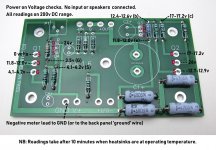
Here is the ACA voltage checks and locations.
I've used easy to reach components as test points to save shorting anything out with the power on. Take your time and use well insulated probes to be extra sure.
The voltages are from 2 boards I built. The Q1, Q2 and Q3 figures are consistent with 'modelled' amps. Q4 is a little different.
Anyone care to measure theirs and let us have a range of 'acceptable' voltages. Or other comments to improve it.
Alan
An externally hosted image should be here but it was not working when we last tested it.
Attachments
OK, I guess it should sound good then 🙂
I live en Aarhus so not really near Kbh. to bad it would have been nice to let somebody else listen to it that know how it should sound.
For preamp I first tried was a B1 but you could really feel the lack of gain. I then tried a Emotiva USP-1 I have just for testing and finally I used the preout of my Hegel. I am not aware what the output impedance is for these I will have to look into that.
How do I find out if it delivers a clean signal?
What do I need of equipment?
If you feel a lack of gain using B1 it could indicate a problem with the amp as it has some gain. Enough gain to deliver some Watts into 8 ohm from just a line signal (e.g. 1 - 2 Vpp). Or you may use <86 dB speakers?
How do I find out if it delivers a clean signal?
What do I need of equipment?
Headphones... if the sound is distorted through the headphones, then the amp has a problem... low impedance headphones - use 100ohm 1W (or higher dissipation) series resistors. High impedance headphones - just connect them straight to the speaker outputs. And don't forget, positive (red) binding posts are the common, negative (black) posts are actual outputs.
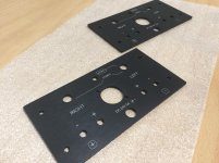
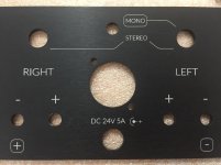
Finally found some time to engrave the back panels. First time I used the laser cutter to do that. I’m very pleased with the result. If you want your BP engraved PM me. As stated before it’s free of charge for the diy community. Only shipping you need to arrange.
Attachments
Finally found some time to engrave the back panels. First time I used the laser cutter to do that. I’m very pleased with the result. If you want your BP engraved PM me. As stated before it’s free of charge for the diy community. Only shipping you need to arrange.
Really nice! Great job. Thanks for the offer to do this for free. That's a wonderful thing to do.
Skylar88, nycavsr2000, Stanislav, eddyvb, thanks for the literature and input on the Capacitance Multiplier. Seems really interesting! A bit above my level right now both in terms of understanding, and physical capacity: I can't cope with more heat right now!
I may end up doing an external 24v linear PSU with the ripple control and output that into a v2 of my chasis that could receive independent power for each channel. In that way I would still get 20V out of it (although there is some conflicting info that it looses 4V PER AMP???) which is what I have now and cannot go beyond due to smaller Heatsinks.
Thanks a lot again for the info! Very nice to learn more about this stuff.
It would be interesting for those building these improvements to be able to comment e results with and without the improvements so it's not just 'it sounds good', but how the ssound differs.
Best regards,
Rafa.
Alan, I think these are invaluable tools for troubleshooting! I won't offer to measure mine as they are biased at 10v instead of 12v, so as not to confuse everyone, but even though I finished mine, his is a great helping hand!Following on from my post # 5600 ACA resistance checks,
Here is the ACA voltage checks and locations...
Thanks,
Rafa.
If you feel a lack of gain using B1 it could indicate a problem with the amp as it has some gain. Enough gain to deliver some Watts into 8 ohm from just a line signal (e.g. 1 - 2 Vpp). Or you may use <86 dB speakers?
I build the ACA to power my frugalhorns.
With the Emotiva the ACA played considerable loader.
I build the ACA to power my frugalhorns.
With the Emotiva the ACA played considerable loader.
To me it seems something is wrong with the ACAs (it is the same with both channels?).
ACA used with horns should be able to play very loud. Even with my 94 dB speakers they play loud.
The Emotiva is an integrated amp which can deliver much more power but with horns you should never reach the limit of the power the ACA can deliver. It could be interesting to check if your ACA has the gain it should. If you set your DMM to AC voltage (maybe set it to measure peaks if this is possible) and measure at the speaker terminals when you are playing and play as loud you can (without distortion…..speakers can be damaged if the amp clips). How many volts do you see? ….and if peak.....with my ACAs I have seen 10V peaks…...when I play very very loud. It was just done as a test to see what the ACAs could do...….and even pushed to this level they played clean.
Really nice! Great job. Thanks for the offer to do this for free. That's a wonderful thing to do.
Really clean Jeffrey! Love the result, Very, very professional looking. Congrats!
Thank you both!
Btw... if you don’t want to diy a CM, you can buy one here. The Allo guys do a great job. This one is also adjustable. This way you don’t loose to much voltage and gain too much heat.
Capacitance Multiplier
Sounds promising... although I have a DigiOne on order that is nearing one month since ordering and have not received it yet.
But yes, that looks nice. I think there is a middle ground between a full DIY and some buying out to get to the destination sooner. I kind of 'spent' a lot of my DIY efforts on the chasis, perhaps I could live with an 'off the shelf' CM! 😉
But yes, that looks nice. I think there is a middle ground between a full DIY and some buying out to get to the destination sooner. I kind of 'spent' a lot of my DIY efforts on the chasis, perhaps I could live with an 'off the shelf' CM! 😉
I Will use these in my ACA’s. Setting the voltage to 200mV which is the noise floor of the SMPS power supply.
I will report my findings.
I will report my findings.
Perhaps the wise ones could help with an observation I've made.
I have a pair of ACAs (1.1 ??) already with the R15 mod.
While playing a pair of KEF LS 50 (that can go down to 3.2 ohms) they sounded better with the 68.1k feedback resistor, regardless of the supply voltage (19 or 24V) and bias (respectivelly 10 and 12 V)
Now, with a pair of TQWT and 8 ohm full range speaker, changing the R12 resistor to 39.2 K seems to sound better.
Is there any logic in this or it is just my imagination ?
Thank you both!
Btw... if you don’t want to diy a CM, you can buy one here. The Allo guys do a great job. This one is also adjustable. This way you don’t loose to much voltage and gain too much heat.
Capacitance Multiplier
I Will use these in my ACA’s. Setting the voltage to 200mV which is the noise floor of the SMPS power supply.
I will report my findings.
Thanks for the tip JeffreyD. I'm with Rafa, the Allo unit looks more at my level. It also means it can sit outside the ACA and do its job, which would be an easy retrofit or (for a first time builder) would avoid having to reconfigure the common bus arrangement inside the ACA.
I'm interested too see what your investigation turns up.
Fellas, it is also very important that your DC bus is connected to the output transistors (located on the PCB) via a bus that has the lowest possible impedance, i.e. via a large, short, thick DC bus bars (if possible)... that DC bus has to deliver a current swing from nothing, to a full required current (at all frequencies, i.e. within a full frequency range of at least 20Hz - 20kHz) in the shortest amount of time possible, while preserving the DC voltage constant. That carefully catered for (inside the amp) current, has to be passed now onto a speaker uninterruptedly (think of the same DC bus requirements, and distances, with regard to your speaker cables!!!)
Imagine a firefighter trying to extinguish the fire by using water from a household tap - this ain't gonna work - hence, the fire hydrants with large diameter pipes in front of the buildings, allowing a very short, large hose connection to release huge water pressure straight onto the fire. The shorter the water chain, a capable water supply of a decent pressure, wide, short hoses... will have a chance.
Using thin wires, multiple connections, crimps, and capacitance multipliers' PCB on various boards with more thin wires... ain't gonna cut it...
Last edited:
build two stereo ACAs
use two channels in parallel (one stereo chassis per loudspeaker)
when you lack output voltage , bridging is the way
when you lack output current , paralleling is the way
or simply build bigger amp
@Zen Mod and Anand.
Thanks, I did not know I can run mono parallel with the ACA. Obviously I would have to switch my layout and loose the balanced xlr 🙁
I built the pair as mono balanced bridged push-pull symmetrical left and right.
Option is to rebuild as mono single-ended parallel. Thinking I may loose flexibility.
Not on a related note, I have a pair of 15,000mfd 50v caps from another project, any harm or benefit in putting those parallel to the input of the smps per chassis?
Last edited:
I know you asked specific people here to answer your question... but my small contribution will go down the line of thinking what is paralleling going to do to input impedance which is already quite low for a single ACA, and requires a dedicated pre-amp with fairly low output impedance (while also trying to minimise that interconnects capacitance...) to get a decent sound out of single ACA
I'll exit now quietly...
I'll exit now quietly...
Last edited:
- Home
- Amplifiers
- Pass Labs
- Amp Camp Amp - ACA