I'll look into rotating the PCB, not completely convinced, although I understand where this is coming from.
I was still thinking of leaving that front 'window' into the interior, so both PCBs facing forward would be better, but that is not something that I'll use to decide. But complexity of assembly may be in the way.
Today was a very long day, but we (dad and I) managed to have the basic 'frame' all cut out and the inner L-profiles are also now mostly finished.
I also bought some thermal paste and still looking for the perforated screen, really hard to find locally, I may need to kill an old computer or HD case 🙂
Here's a couple of (real) pictures of the progress done today:


We had a minor setback as our electric saw (sorry, no idea what is the name in English) has developed a sideways-movement, and we had to have the 'straight' cuts done on a metal shop, and the 'secondary' cuts done by hand, so I spent most of the day with a small metallic saw chopping away 2mm aluminum. Not hard, but its not the usual 0.8mm sheet that cuts like butter.
Hopefully tomorrow the case will be mostly secured (as is may last day of vacation) and the soldering and smaller work can be done after job hours and during weekends.
I'm happy with how it's turning out (or the idea of how it may turn, as it is too early to tell)
Thanks once more for all the feedback and ideas, I really appreciate it.
Best regards,
Rafa.
I was still thinking of leaving that front 'window' into the interior, so both PCBs facing forward would be better, but that is not something that I'll use to decide. But complexity of assembly may be in the way.
Today was a very long day, but we (dad and I) managed to have the basic 'frame' all cut out and the inner L-profiles are also now mostly finished.
I also bought some thermal paste and still looking for the perforated screen, really hard to find locally, I may need to kill an old computer or HD case 🙂
Here's a couple of (real) pictures of the progress done today:
We had a minor setback as our electric saw (sorry, no idea what is the name in English) has developed a sideways-movement, and we had to have the 'straight' cuts done on a metal shop, and the 'secondary' cuts done by hand, so I spent most of the day with a small metallic saw chopping away 2mm aluminum. Not hard, but its not the usual 0.8mm sheet that cuts like butter.
Hopefully tomorrow the case will be mostly secured (as is may last day of vacation) and the soldering and smaller work can be done after job hours and during weekends.
I'm happy with how it's turning out (or the idea of how it may turn, as it is too early to tell)
Thanks once more for all the feedback and ideas, I really appreciate it.
Best regards,
Rafa.
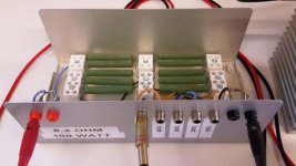
Here we go. This is the load resistor that I built for measuring the ACA. Should have done this way earlier already. It's not the most elaborate one and only good for around 30W continuous dissipation (running at more than 100 degrees Celsius), but it gets the job done and wasn't overly expensive. I used 10 identical resistors in series, so that I can conveniently tap the output every 10% as not to overload the soundcard input with too huge output swings. Initially I had planned to pick a 1.0R 25W and a 3.9R 7W in parallel instead of a single 0.82R resistor for a total resistance more close to 8.0R and even more power handling, but then again I would have needed a large heat sink and a bigger case, ..., more expensive, ..., you name it 🙄.
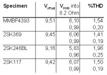
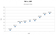
These are the results for a couple of devices (didn't test them all):
As you can see, there are actually some differences in THD between the different JFETs. All in all I find them to be rather insignificant though 😱.
I started out with the MMBF4393, because it was still in circuit. While setting everything up, the amp had some time to warm up. First thing I did then was to find the optimum offset point. I adjusted the soundcard level until the amplifier output started to distort visually on the scope and then backed up a little. This was the case with -10dBFS output, yielding around 1.50%THD into the 8.2R load. I then adjusted the potentiometer for minimum THD. Optimum offset was around 9.5V with 20.75V supply voltage. With a couple dBFS less input voltage the optimum offset voltage shifted a little; with 16dBFS less (or -26dBFS absolute) this made almost no difference anymore, so the -10 optimum was also optimum for -26. -10dBFS resulted in 6.1V RMS into 8.2R and -26dBFS resulted in almost 1V RMS into 8.2R. I arbitrarily chose those those two points for my measurements, because I don't have a fancy automated software suite at my disposal.
So -26dBFS yield 0.20% THD with the MMBF4393. I then swapped in the 2SK369 as the next DUT and fired up the amp again, without touching the potentiometer. After 'booting up' for half a minute, I measured the exact same 0.20% THD, but this time with an offset of 12.34V! Looks almost as if the THD is dependent on the pot position, but that would be a little strange
 . Readjusting for 9.45V offset the THD dropped a little, down to 0.19%. As you can see, with small output levels the offset voltage is not that critical at all, but of course you'll make sure that it's optimum as to not compromise full output swing.
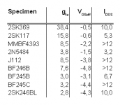
Increasing the input level to -10dBFS then showed a somewhat better THD of 1.41% compared to prior 1.51%. The worst of my devices, the 2SK246, only managed 1.96%. Another part I accidentally found in my bin, the 2SK117 with a gfs of 18, performed just a little better than the MMBF and only slightly worse than the 2SK369.
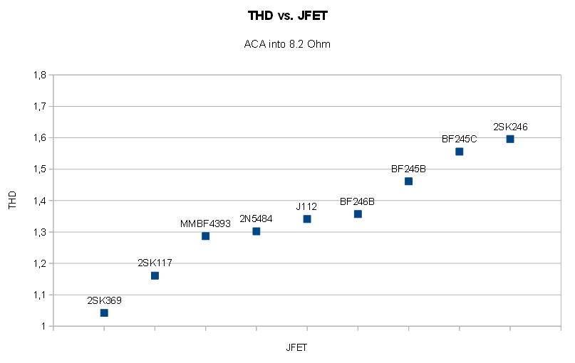
As a conclusion I would say that you can easily substitute the rare and expensive 2SK170 with some cheaper, more readily available JFET devices without compromising the quality of this nice little amp!
Here's a quick THD versus Input Level graph. I simply clicked through the soundcard output level in 1dBFS steps and took a THD reading. Nothing terribly new 😉.
Attachments
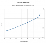
So now you know why it sounds good...because with decreasing signal, distortion gets lower and lower. As it should for class a amp.
Does not matter what distortion amp has at maximum power, when at normal listening levels signal crosses zero countles times with minimum damage.
Does not matter what distortion amp has at maximum power, when at normal listening levels signal crosses zero countles times with minimum damage.
So now you know why it sounds good...because with decreasing signal, distortion gets lower and lower. As it should for class a amp.
Does not matter what distortion amp has at maximum power, when at normal listening levels signal crosses zero countles times with minimum damage.
As is so wisely stated on the store website
"HOW DOES IT SOUND?
Once you build the Amp Camp Amp you'll never look at power and distortion figures the same way again."
Using an active crossover and loaded into speakers with 96db of sensitivity. The ACA's make lots of music at tenths of 1 watt. It sounds great!
So now you know why it sounds good...
Didn't listen to it just yet 😱😀!
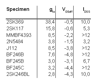
Found some time this afternoon and re-ran the THD test, now with all my JFETs at hand. Input was -12dBFS or 0.954V RMS, for an output of 4.8V RMS into 8.2 Ohm, or almost 3W. Offset was re-set to 9.5V for every JFET. Here are the final results:
Attachments
Last edited:
I don’t think Nelson’s primary goal was to design a circuit that would be this affordable just to be measured. To borrow from Joe Rasmussen- JLTI
Didn't listen to it just yet 😱😀!
Found some time this afternoon and re-ran the THD test, now with all my JFETs at hand. Input was -12dBFS or 0.954V RMS, for an output of 4.8V RMS into 8.2 Ohm, or almost 3W. Offset was re-set to 9.5V for every JFET. Here are the final results:
What's happening in the FIRST WATT?
The first watt is just like the third, only a little less 😉
And of course I didn't just build the amp to measure it, but I will finish the second channel before I give them a thorough listen.
And of course I didn't just build the amp to measure it, but I will finish the second channel before I give them a thorough listen.
The first watt is just like the third, only a little less 😉
And of course I didn't just build the amp to measure it, but I will finish the second channel before I give them a thorough listen.
You may be wasting your time...
Replacement For Toshiba 2SK170/2SJ74
The stickiest sticky...by ZM
I just tried for the first time using the ACA with a real active preamp. I used the preamp part of a Nad M3 (my only real preamp). It should be a good low noise preamp built with JFETs input class A stage. This took ACA to a new level. So I am now convinced I need to build a preamp. Maybe when the B1 with Korg tube is ready? B1 Korg amp has some gain?
For the first time I felt that the ACA could compete with my 300b amp. Bass response got more detailed when the active preamp was connected. This was a surprise.
For the first time I felt that the ACA could compete with my 300b amp. Bass response got more detailed when the active preamp was connected. This was a surprise.
I just tried for the first time using the ACA with a real active preamp. I used the preamp part of a Nad M3 (my only real preamp). It should be a good low noise preamp built with JFETs input class A stage. This took ACA to a new level. So I am now convinced I need to build a preamp. Maybe when the B1 with Korg tube is ready? B1 Korg amp has some gain?
For the first time I felt that the ACA could compete with my 300b amp. Bass response got more detailed when the active preamp was connected. This was a surprise.
The output of my DAC (Balanced) spec is +6 dBV. It gets along unbelievably well with the input of the AAC in the balanced configuration.
Hello ACA fans. I’m sitting back with my feet up here on Fathers Day enjoying my ACAs pumping out some Tito Puente and friends.
My enjoyment of the moment was made possible because this morning I sorted out a ground loop issue in my system that was driving me crazy. The amps and system are now silent to my ears between tracks even if I stick my head inside my horns.
Before I figured out I had a ground loop that was causing hum, I was working on a different power supply for the ACAs. I would still like to give it a try.
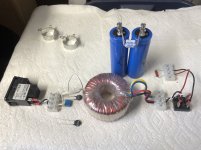
I want to use components I have on hand and have been working on following the power supply schematic from the F1 amp service manual. I was going to just bread board it point to point first and then decide if it was worth casing up. I have a few questions/issues.
The transformers I have on hand are surplus units from Apex Jr. They only have a single primary connection and have dual 24 volt secondaries (actually they measure 25.4 volts when I hooked them up to a fused power inlet and tested them earlier). I bought them originally to use with some gainclone kits, of which I built one stereo version and enjoyed it until I got my ACAs working. I would still like to give it a try.
My first question is how do I handle the thermistor that is supposed to deal with the in-rush current since I only have a single primary winding on the transformer? Do I only install one thermistor on either the 0 or 120 leg from the incoming AC? Do I put a thermistor on both the 0 and 120 legs? Is it not possible to follow the F1 schematic without a dual primary transformer?
My second question is what can I expect the actual output voltage to be from this supply (with these 24V secondaries) after regulation and the CRC bank and what changes might I have to make to the circuit to handle the higher voltage and I’m assuming higher heat dissipation requirements?
For reference, I am using the 24V Meanwell supplies that are being sold for the current ACA kits. My amps are built with the mono block chassis originally sold in the DIYAudio store for the ACA project in combination with the version 1b boards which have R15 present and R12 modified value installed.
I attached an image of the F1 supply schematic and the majority of the components for the supply that I had begun to layout trying to follow it. It is incomplete as far as wiring especially in the CRC segment.
Any guidance that can be offered would be greatly appreciated.
My enjoyment of the moment was made possible because this morning I sorted out a ground loop issue in my system that was driving me crazy. The amps and system are now silent to my ears between tracks even if I stick my head inside my horns.
Before I figured out I had a ground loop that was causing hum, I was working on a different power supply for the ACAs. I would still like to give it a try.
I want to use components I have on hand and have been working on following the power supply schematic from the F1 amp service manual. I was going to just bread board it point to point first and then decide if it was worth casing up. I have a few questions/issues.
The transformers I have on hand are surplus units from Apex Jr. They only have a single primary connection and have dual 24 volt secondaries (actually they measure 25.4 volts when I hooked them up to a fused power inlet and tested them earlier). I bought them originally to use with some gainclone kits, of which I built one stereo version and enjoyed it until I got my ACAs working. I would still like to give it a try.
My first question is how do I handle the thermistor that is supposed to deal with the in-rush current since I only have a single primary winding on the transformer? Do I only install one thermistor on either the 0 or 120 leg from the incoming AC? Do I put a thermistor on both the 0 and 120 legs? Is it not possible to follow the F1 schematic without a dual primary transformer?
My second question is what can I expect the actual output voltage to be from this supply (with these 24V secondaries) after regulation and the CRC bank and what changes might I have to make to the circuit to handle the higher voltage and I’m assuming higher heat dissipation requirements?
For reference, I am using the 24V Meanwell supplies that are being sold for the current ACA kits. My amps are built with the mono block chassis originally sold in the DIYAudio store for the ACA project in combination with the version 1b boards which have R15 present and R12 modified value installed.
I attached an image of the F1 supply schematic and the majority of the components for the supply that I had begun to layout trying to follow it. It is incomplete as far as wiring especially in the CRC segment.
Any guidance that can be offered would be greatly appreciated.
Attachments
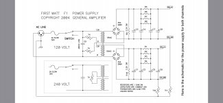
Look at just the top of the F1 supply schematic and try to copy that... as the circuit is two supplies in parallel, you only need to make one.
Place the thermistor in series with one of the transformer primaries.
Voltage, however, is going to be an issue, 24VAC rectifies to 33.6VDC as there’s a 40% gain, and although you’ll lose a volt or two in the bridge, you’ll still have something around 32VDC, and that’s going to be too high for this project.
Keep it for another project, it’s a nice collection of stuff. 🙂
Look at just the top of the F1 supply schematic and try to copy that... as the circuit is two supplies in parallel, you only need to make one.
Place the thermistor in series with one of the transformer primaries.
That is what I had started trying to do when I was laying out the components and realized I only had a single primary transformer.
I’m assuming you meant to place the thermistor in series with either the 0 or 120 wire of the single primary I have on my transformer?
My understanding, or lack of thereof, the proper terminology used here is probably getting in the way...sorry for that. I’d just like to know if I have the filtering cap and thermistor laid out properly in the picture based on your response.
Voltage, however, is going to be an issue, 24VAC rectifies to 33.6VDC as there’s a 40% gain, and although you’ll lose a volt or two in the bridge, you’ll still have something around 32VDC, and that’s going to be too high for this project.
Keep it for another project, it’s a nice collection of stuff. 🙂
I suspected this would be the answer.
I have some larger dual primary18V secondary transformers I bought to build the F2. I was thinking of building them in a separate chassis so they could be tried with either the ACA or F2 via an umbilical system.
I think I was more interested in testing my abilities to follow a schematic properly and put together a power supply without having to use a PCB here.
I suppose this supply could be used with a “Stage 1” F5 that I read about it the turbo article using upgraded resistors and the like...although I did buy some big 24V Antek transformers for that idea when they had their “fire” sale. Those would be used as amps for my low frequency drivers in my active system.
Need to find another cool project that needs a 32V supply I guess.
Troubleshoot Low Volume
I need some help with my original ACA build, done Nov 2016. I just noticed that the right channel has much lower volume than the left. I have done some basic stuff - switched speakers, switched power supplies. I've eliminated the speakers and power supplies, and know that it is the right ACA.
Any assistance would be appreciated......but please know that I'll need some hand-holding here. I did do a search on this thread, and found one reply to a troubleshooting request. "Easy, check your voltages, work thru your schematic." Apparently that worked for the other poster, but I would need some pointers on how to do that. Maybe there is an article or two you can point me to?
I do know how to use a multimeter, but I don't want to go poking around inside my ACA and end up causing more problems than I fix. Which I admit I have a history of doing on other things I have worked on......
On a happier note, just got word from diyAudio that my ACA enclosures for my latest order are on on their way!
Last edited:
for starters , check all resistor values on bad channel
in fact - check both channels against schematic
in fact - check both channels against schematic
Thanks Zen Mod. To confirm, I turn it off, unplug it, open the case, and use the multimeter to check that resistors are same as spec. If not, then replace ones that are not to spec?
- Home
- Amplifiers
- Pass Labs
- Amp Camp Amp - ACA