Yes, I would sure check one channel with all the different combinations of the 4 tubes. Since you did not touch the pre amp section or power section, hard to fathom it is anything there. Also, if you really had to heat the solder a long time to get the tubes out, the heat could have damaged a nearby resistor or diode (25, 26, 502, 503). I would first think it could be a tube issue.
AMC CVT-3030 shooting from speakers, blowing fuse
Suggest U check above thread or communicate with its author.
Suggest U check above thread or communicate with its author.
I would also check this url. Make sure pins 1 and 8 are connected to ground. Were there any wires running off those pins to each other or to ground when you de-soldered them?
Red plating AMC CVT-3030 has me puzzled | Audiokarma Home Audio Stereo Discussion Forums
Good luck.
Red plating AMC CVT-3030 has me puzzled | Audiokarma Home Audio Stereo Discussion Forums
Good luck.
You might very well have rotated sockets and now filaments short +V to ground or some other gross error.
Agree. The sockets look aligned and off the same side of the board as were the soldered tubes. Lots of reviews and upgrades out there about this amplifier. Looks like there were several iterations of boards, with a few design changes. There are also different fuses used, so if you had not touched fuses, you would presumably be fine, but if you removed some, make sure the right fuses are in the right locations.
Hi everybody,
Thanks for the many comments and suggestions.
Here some clarifications:
Hopefully during next week I will be able to have the tubes tested. That should give clearer picture.
If you have any other ideas, I am happy to hear!
Thanks again,
Fabrizio
Thanks for the many comments and suggestions.
Here some clarifications:
- The problem relates to the tube modules only as I already could exclude supply and preamp
- The sockets are correctly in place
- The film caps I replaced are correct (0.1u and 250V). I woud be very suprised if these were a cause but I will check with the old ones once I get more fuses
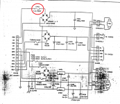
- The fuse blowing is on B+ (see pic), 1A 250V, right before the rectifier. No wrongdoings here with spare fuses.
- I desoldered the tubes using a lot of braid and gently using pliers to get pins unstucked. I cleaned the pins from solder as well as with nail polish to make them slide properly into the sockets. I don't think I applied too much heat but I will know for sure once I will have the tubes tested.
- Heat did not damage any closeby parts such as resistors or diodes
- No wires were present to connect pin 8 and 9 to gnd. They are connected through the pcb
Hopefully during next week I will be able to have the tubes tested. That should give clearer picture.
If you have any other ideas, I am happy to hear!
Thanks again,
Fabrizio
Attachments
Thanks a lot Scott, I have that already. I've done so much work on the amp in the past couple months I know the manual almost by heart ;-)
It seems somewhat likely the PCB is damaged. I’d check for a short between plate tracks and ground and also screen tracks and ground. I’d recommend a hi pot test of some sort.
I parted one of these out a few years ago. I suspect I have a copy of that PCB around some where. If you find that to be the problem, I’d be happy to search for it. I also have the PT too.
I parted one of these out a few years ago. I suspect I have a copy of that PCB around some where. If you find that to be the problem, I’d be happy to search for it. I also have the PT too.
Thanks Dave,
I already checked for shorts in between the sockets contacts (including the ones connected to gnd) and everything is ok.
I already checked for shorts in between the sockets contacts (including the ones connected to gnd) and everything is ok.
I think you need to test the voltages for sure per the manual. In an amp with tubes, electronic parts and a pcb of that age, something could certainly have happened to one of the parts when you were soldering. Maybe not so likely in your mind, as you were careful, but it could. If your tubes prove to be good and the caps are good, then you will have lots of investigating to do. I would also check to make sure all the plastic connectors, wires leading into them, and pins and sockets in them are looking good. Sometimes in removing the connectors the wires or pins can go awry. Did the plastic connectors come apart easily or did you really have to yank on them, or yank on the wires? Good luck. I am sure it is frustrating the heck out of you. Do you have a variac so you can power it up slowly while checking voltages?
The socket orientation looks correct with the keyway in the PCB and missing pin 6 on the board shown anyway. Which are the new caps? Have you tried one board at a time with tubes in to narrow it down?
Oh yeah, are you using the same tubes or new tubes?
Oh yeah, are you using the same tubes or new tubes?
I’m using same tubes EL34G. By the way is it ok to plug in one tube at a time on each module? Thanks!
I would suspect damaged tubes (pin connections) if you’re using the same ones. I was thinking test one channel at a time. If you run one tube per side you can magnetize the transformer.
Yes, I’ve been testing each channel (1 module, 2 tubes in push pull) at time.
Beyond checking for shorts on the tubes (which I did with no results) next test is to use a dedicated tester?
Beyond checking for shorts on the tubes (which I did with no results) next test is to use a dedicated tester?
yes but the maps are very simple to track, so it is sufficient, with the diagram, to check if the supports are well oriented.
Check pin 5 without the tubes in to see that you have a negative bias voltage on that pin. Didn't see what your B+ was but around -20 volts or so on each tube.
- Home
- Amplifiers
- Tubes / Valves
- AMC CVT3030