So, I substituted both diode and mosfet but nothing has changed.
The two components are fine.
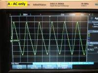
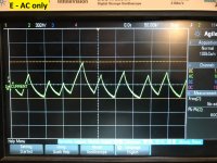
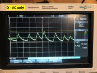
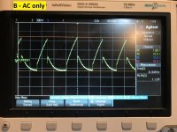
Refer to the oscilloscope pics with Vin(A) and Vout(E).
To recap, the regulator exhibits the same behavior
Even if Vds is higher and the mosfet has more room to regulate, the output is still not stable.
In addition, when the voltage divider is in place, Vgs drops down to .4V
The two components are fine.
Refer to the oscilloscope pics with Vin(A) and Vout(E).
To recap, the regulator exhibits the same behavior
- In both variants: with or without gate voltage divider
- With R3 (47ohm) bypassed or not
Even if Vds is higher and the mosfet has more room to regulate, the output is still not stable.
In addition, when the voltage divider is in place, Vgs drops down to .4V
Attachments
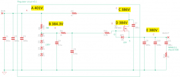
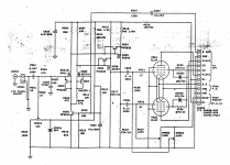
PS: I am adding a couple more measure points on the circuit without voltage divider.
I noticed that when I turn on the amp the regulator works fine and once the tubes are hot enough to draw more current, the output voltage (E) starts to wander
This is also in line with another test I did, with a couple resitors as load (8k and 15k) where the output voltage stays very flat and everything works just fine
Attachments
Regulator works!
Dear all,
Happy to share that I got the regulator to work correctly.
The main problem was related to the zener chain not being able to regulate. In fact the difference between the Vin (A) and the zener chain voltage was too little.
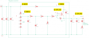
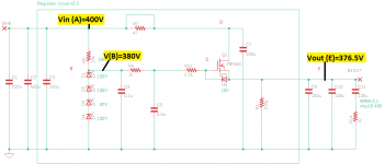
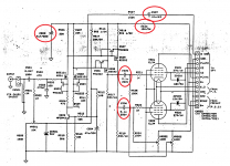
In the schematic attached you can see that I substituted one 100V zener with an 82V zener and used an 18k resistor to obtain the right regulating current.
In the end the nominal B+ voltage has to be 375V so there was enough room to reduce the zener voltage.
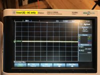
Also, I bypassed R3.
Now the ripple is gone for good!
The only little concern I have is the power dissipated by the mosfet which is around 6.3W (I~260mA)
The heat exchanger gets quite hot - around 70C - so I might consider to add R3 again to dissipate some of that power.
Other than that, do you have any other suggestions to improve performance and/or reduce part count/footprint?
Thanks again!
Fabrizio
Dear all,
Happy to share that I got the regulator to work correctly.
The main problem was related to the zener chain not being able to regulate. In fact the difference between the Vin (A) and the zener chain voltage was too little.
In the schematic attached you can see that I substituted one 100V zener with an 82V zener and used an 18k resistor to obtain the right regulating current.
In the end the nominal B+ voltage has to be 375V so there was enough room to reduce the zener voltage.
Also, I bypassed R3.
Now the ripple is gone for good!
The only little concern I have is the power dissipated by the mosfet which is around 6.3W (I~260mA)
The heat exchanger gets quite hot - around 70C - so I might consider to add R3 again to dissipate some of that power.
Other than that, do you have any other suggestions to improve performance and/or reduce part count/footprint?
Thanks again!
Fabrizio
Attachments

Have you confirmed there is any advantage achieved with the extra RC filter stage for gate circuit? Or the alternative, if there is any damaging start-up FET dissipation that would exceed SOA limit?
Have you worked out what heatsinking you will need to cover mains high ACV, with respect to Tj and where you will place this heatsink?
Have you looked at what would happen if a part in the amp failed and the supply drew noticeably higher current?
Have you worked out what heatsinking you will need to cover mains high ACV, with respect to Tj and where you will place this heatsink?
Have you looked at what would happen if a part in the amp failed and the supply drew noticeably higher current?
Capacitors replacement for tube stage
Dear community,
I am reviewing an old modification (very poorly executed…) that was done on the two tubes modules representing the final stage of my hybrid AMC CVT3030 amp.
I don’t have those modules anymore and I am thinking of applying the same mod to the present ones since it’s only about replacing four capacitors and one resistor.
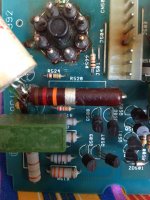
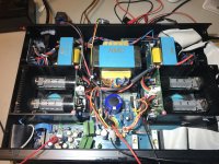
I highlighted in the schematic the components that were changed and I am adding also some pictures.
Could you please take a look, possibly indicate if the changes make sense to you and which capacitors I should buy?
For instance, I could not find online the green Russian caps but I’m sure there are good alternatives.
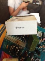
C507: 10k100 white bulky cap, no idea what that is
C502: 3u3 400vdc +/- 3% Mundorf MCAP
R520: 12k
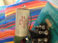
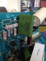
C505 / C506: K71-7 0,1 mk +/- 2% 250B8604 green Russian caps
Thanks a lot in advance
Fabrizio
Dear community,
I am reviewing an old modification (very poorly executed…) that was done on the two tubes modules representing the final stage of my hybrid AMC CVT3030 amp.
I don’t have those modules anymore and I am thinking of applying the same mod to the present ones since it’s only about replacing four capacitors and one resistor.
I highlighted in the schematic the components that were changed and I am adding also some pictures.
Could you please take a look, possibly indicate if the changes make sense to you and which capacitors I should buy?
For instance, I could not find online the green Russian caps but I’m sure there are good alternatives.
C507: 10k100 white bulky cap, no idea what that is
C502: 3u3 400vdc +/- 3% Mundorf MCAP
R520: 12k
C505 / C506: K71-7 0,1 mk +/- 2% 250B8604 green Russian caps
Thanks a lot in advance
Fabrizio
Attachments
Thanks trobbins, I will definitely look into that. Until now my priority nr.1 was to reproduce the functionaly of an old, awfully executed mod.
This modification appears to be executed by an overzealous audiophool who didn't really know what he's being doing. Waaay too bulky capacitors with waaay too long leads! I suppose he has solved non existing issues by introducing new ones.
If the original non-polarized caps were film caps, and the polarized ones were 'lytics of good quality and in good shape, I don't see any necessity for altering anything at all. And there's also really no necessity to replace a - most probably - wire wound resistor by a sub-par carbon composite one.
Perhaps you might want to desolder those EL34's and put them in appropriate sockets?
Best regards!
and while doing so, take the el34 out of their heat sink and put them vertically, turn this ridiculous connector and replace it with wires.
this amp (and for having had more repair) is a nightmare of engineering and is even ridiculous given the size of the box.
if you want to do something good, look at the diagram, put the original components back and change it to remove the sinks and connectors
this amp (and for having had more repair) is a nightmare of engineering and is even ridiculous given the size of the box.
if you want to do something good, look at the diagram, put the original components back and change it to remove the sinks and connectors
C502 should be a small electrolytic 4u7F 350volts; Aluminium Capacitors | RS Components
C507 10uF 63v ; Aluminium Capacitors | RS Components
C505/6 100nF 250v ; Polyester Film Capacitors | RS Components
And R520 15k 5W ; Through Hole Fixed Resistors
All samples are to give you the type of component required. Mouser will carry stock.
Don't forget to make good the burning connector, (pin 4) is probably for the heaters and is being over loaded.
Last edited:
C505/C506 are polystyrene. Good stuff, but heat sensitive. This listing is exactly what you're looking for.
The schematic clearly shows (via the + sign) that electrolytic parts are OEM for C502 and C507. C502 is a PSU decoupling part. The silly expensive Mundorf part is (IMO) a bad idea, if only for mechanical reasons. This part should be (electrically) an improvement over OEM, without creating as many problems as it solves. C507 appears to be part of a NFB loop and a film part makes sense, but size and cost operate strongly against that selection. Working with PCBs leaves little "wiggle room". Once again, a high grade 'lytic, like this, may be the best way forward.
The photo suggests that a 10% tolerance carbon composition part is OEM for R520. This part is a definite upgrade (less noise/no drift).
I agree with the installation of sockets suggestion, for the EL34s.
C502 should be a small electrolytic 4u7F 350volts; Aluminium Capacitors | RS Components
C507 10uF 63v ; Aluminium Capacitors | RS Components
C505/6 100nF 250v ; Polyester Film Capacitors | RS Components
And R520 15k 5W ; Through Hole Fixed Resistors
All samples are to give you the type of component required. Mouser will carry stock.
C507 10uF 63v ; Aluminium Capacitors | RS Components
C505/6 100nF 250v ; Polyester Film Capacitors | RS Components
And R520 15k 5W ; Through Hole Fixed Resistors
All samples are to give you the type of component required. Mouser will carry stock.
Dear all, … In the schematic attached you can see that I substituted one ¹⁰⁰V zener with an ⁸²V zener and used an 18k resistor to obtain the right regulating current. In the end the nominal B+ voltage has to be ³⁷⁵V so there was enough room to reduce the zener voltage. Also, I bypassed R3. Now the ripple is gone for good!
The only little concern I have is the power dissipated by the MOSFET which is around 6.3W (I=260mA) The heat exchanger gets quite hot - around 70°C - so I might consider to add R3 again to dissipate some of that power.
Other than that, do you have any other suggestions to improve performance and/or reduce part count/footprint? Thanks again! Fabrizio
Good job, friend.
As you found out, it isn't just important that the gate be driven with a clean, smooth, no-ripple voltage, but also that it be driven with a voltage well below the minimum "ripple-side" voltage on the drain of the MOSFET.
Its called "headroom".
Thanks for all the oscillographs.
GoatGuy
Hum on one channel of hybrid amp
Dear all,
After the succesful rebuild of a B+ regulator (Help with B+ supply mod (gyrator?)) I am now facing a hum on the right channel of my AMC CVT3030 amp.
There is moderate 120Hz hum (see pic below) for which I cannot identify the source.
The hum is always present, is not affected by the volume level and the audio signal works fine.
The hum is present only when a signal cable from the preamp is connected to the right tube stage.
However, I cannot measure anything on the tube input (CN501) and switching L/R channels from the preamp does not change anything either (meaning that the hum is present as soon as a signal cable connects to the tube module)
Any suggestion?
Thanks again
Fabrizio
Attachments

Last edited:
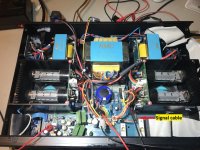
The hum is present only when a signal cable from the preamp is connected to the right tube stage.
Replace the wire from each input RCA ground shell to the circuit common with a 10R resistor.
Thanks rayma,
As I am not very familiar with audio electronics, I am not sure I understand correctly what I should do. Do you mean there is a ground wire on all RCA inputs (CD, AUX etc) at the back of the amp, which I should replace? Until the mishap with mod (see referenced thread above) eveything was working fine.
Thanks again,
Fabrizio
Last edited:
there is a the ground wire on all RCA inputs (CD, AUX etc) at the back of the amp, which I should replace?
Any time you alter the circuitry, there can be problems caused by the changes. The amplifier has to be designed as a whole. Can you post a photo of the chassis inside near the input sockets?

120hz comes from the power supply, may be a ground loop or loose connection.
it is good that it disappears when cable is disconnected.
your amp is the reverse of mine, Tube preamp and tone controls > SS mosfet poweramp
it is good that it disappears when cable is disconnected.
your amp is the reverse of mine, Tube preamp and tone controls > SS mosfet poweramp
- Home
- Amplifiers
- Tubes / Valves
- AMC CVT3030