Desoldering tubes from PCB
Hi!
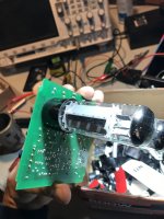
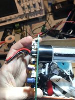
I am trying to desolder tubes from a PCB in order to put proper sockets.
After having eliminated solder from the contacts with pump and braid, the tubes are still completely stuck.
I wonder what to do next as I am afraid a heat gun would damage both tubes and PCB.
Any further suggestion?
Thanks
Fabrizio
Hi!
I am trying to desolder tubes from a PCB in order to put proper sockets.
After having eliminated solder from the contacts with pump and braid, the tubes are still completely stuck.
I wonder what to do next as I am afraid a heat gun would damage both tubes and PCB.
Any further suggestion?
Thanks
Fabrizio
Attachments
WOW, the fitting of valves like that is not a good thing and prone to issues!
I would grab each pin in turn, with small pliers and move the pin around until free. Do that to all of the pins and then all that will be holding it down is the plastic base. Gently ease, with a small screwdriver blade, each side away from the board.
This is why valves are never fitted to the boards like that and have valve bases.
Only wire-ended valves should be directly soldered to a PCB. Many of these were designed to work once, for a few seconds, before being blown to pieces.
Try melting the remaining solder, one pin at a time, then as it solidifies wiggle the pin with pliers. The aim is to turn a good joint into a poor joint, which may then be more easily broken.
Try melting the remaining solder, one pin at a time, then as it solidifies wiggle the pin with pliers. The aim is to turn a good joint into a poor joint, which may then be more easily broken.
Having a solder sucker and a flux pen helps. Reflow the pins one at a time with fresh solder as said. Desoldering braid might help. The pins are strong so are hard to wiggle a crack around them. Not much wiggle room to play with judging by the unsoldered pin.
I've never seen an octal type valve directly soldered in, their pins might be hollow.
I've never seen an octal type valve directly soldered in, their pins might be hollow.
Last edited:
Personally, I would consider the tube a write-off. The pins will be coated in solder, which may be too difficult to safely remove completely, resulting in oversized pins. Oversize pins could stretch the new socket, rendering it less reliable for subsequent tubes.
By the time you get it heated enough to remove the tube, even one pin at a time, the board is going to be a wreck. You may have to decide which is more valuable, the board or the tube, and sacrifice the other.
The amount of time required for a clean removal, even at $3.50 am hour, would likely pay to replace everything.
The amount of time required for a clean removal, even at $3.50 am hour, would likely pay to replace everything.
The only way to get multi pin components out of a pcb is to remove them one pin at a time.
Obviously with a valve they are held together with the plastic base.
I would hack saw through the plastic base to get at the top of the pins and cut the plastic around each pin. Once a pin is free heat it up, put plenty of solder around the pin then pull it out quick with long nose pliers.
And next time use a valve socket !
Necessity is the mother of invention 🙄
Perhaps making a mask out of a silicone coaster. Drill holes in it and slide it over the pins. The pcb should be protected. Heat can then be applied via a heat gun heating all the pins at once. Don't forget the flux
Perhaps making a mask out of a silicone coaster. Drill holes in it and slide it over the pins. The pcb should be protected. Heat can then be applied via a heat gun heating all the pins at once. Don't forget the flux
Now that you removed most solder from around the pins, you just have to push the tube from the bottom straight upwards. Apply axial force to the black plastic part. Do not wiggle, it will damage the PCB tracks. The solder residue will give up at one point.
The output valves will need to be sacrificed. Just wiggle them via the glass bulb until the glue bond to the plastic base, fatigues and continue until the lead out wires to the pins give way. It looks like you have a version of the AMC CVT 3030 amplifier to fix and if you intend to fit octal sockets to the PCB then you will have to cut away some of the heatsink to allow clearance for the EL34s.
Valve pins/PCB has too much solder, your copper braid has not enough solder flux, just put more flux, e.g. solid flux diluted with isopropyl alcohol.
Another solder/desolder cycle would be useful.
Be careful with the copper on the PCB, it could damage with an excess of heat.
Excess flux can (MUST) be cleaned with paint thinner or acetone for nails.
Another solder/desolder cycle would be useful.
Be careful with the copper on the PCB, it could damage with an excess of heat.
Excess flux can (MUST) be cleaned with paint thinner or acetone for nails.
Last edited:
I have seen this in AMC 30XX tube amps. They after that added socket with the S version.
A PITA for sure to remove. I would break the valve, and cut the base with a hand tool rotary saw, and remove pin by pin carefully while heated with an iron, else you will tear the inside of the PCB hole metal coating.
A PITA for sure to remove. I would break the valve, and cut the base with a hand tool rotary saw, and remove pin by pin carefully while heated with an iron, else you will tear the inside of the PCB hole metal coating.
<snip>
And next time use a valve socket !
This appears to be an amplifier output assembly from an AMC CVT-3030. (Not a diy project)
Watch out that whatever socket you install provides enough clearance between new tubes and casework, it's tight.
Dear all,
Thanks for the many suggestions.
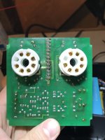
In the end I managed with some patience, pliers and a lot of braid.
It is indeed the power stage of an amc cvt 3030 and yes, I’ll cut out the heat sinks to accommodate the modules with sockets and tubes.
Cheers
Fabrizio
Thanks for the many suggestions.
In the end I managed with some patience, pliers and a lot of braid.
It is indeed the power stage of an amc cvt 3030 and yes, I’ll cut out the heat sinks to accommodate the modules with sockets and tubes.
Cheers
Fabrizio
Sorry I'm late to the party here, but the best solution for this problem would likely be a low-temperature solder additive like Chip Quick or Fast Chip. Once applied, it reduces the melting temp of the remaining solder so much that the tube would simply fall out after re-heating all of the joints.
Dear all,
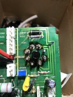
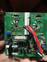
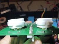
I own an AMC cvt3030 amp which has two tube modules as power output stage. I recently put sockets on the two modules (the tubes were originally soldered to pcb) and changed coupling capacitors (see pics below of one module).
Now the B+ supply fuse pops up every time either of the two modules is connected, with the tubes attached. If I take the tubes out then no problem.
I visualy inspected the tubes and measured for any shorts with a multimeter and everything is ok. Also, I checked the sockets contacts and no short there either.
Any idea on what is happening?
Thanks
Fabrizio
Attachments
Last edited:
Did you use the same specs/voltage rating for the new caps? What type of caps? Are you certain that the tube sockets are in the correct orientation? What type of fuse are you using. New fuse or the original fuse? Tubes could have been damaged by the heat applied when de-soldering them from the board. EL-34 tubes, right? Two per channel? MOSFET pre-amplification with tube out, right? Did you measure the voltages in the tube sockets when no tubes were attached? (be very carefull when measuring the B+!). Do you know of another person with an EL34 amp you could go try your tubes in?
Also, how difficult was it to de-solder the tubes? Did you have to apply the iron for a long time to get them free? Did you get all the solder off of the tube pins? Did you have to work them hard and bend pins to pull them out? That could certainly be an issue.
- Home
- Amplifiers
- Tubes / Valves
- AMC CVT3030