Two separate 150W SMPS could be used to power a monobloc.1. The AN amplifier will need an power supply with +/- voltages; hence the 24V 5A power supplies will not work.
I used two separate 350W SMPS for a dual channel AN 8ohm (here).

vbutani,
+1 Jacques. You can use two Meanwell supplies as long as the AC earth is separated from the -ve output so you can connect as a split supply. A simple check with a meter. I am using just such an arrangement at the moment too, there's a trimmer that you can set the voltage on on mine so 20V no problem. BUT 120w for two channels is not enough, the rating is optimistic for audio... you'd need to get another pair and maybe look at not biasing for the full 3A for a bit less power. Depends on how big your room is, how loud and how close you listen. The fans will drive you mad too. Budget for swapping those out.
+1 Jacques. You can use two Meanwell supplies as long as the AC earth is separated from the -ve output so you can connect as a split supply. A simple check with a meter. I am using just such an arrangement at the moment too, there's a trimmer that you can set the voltage on on mine so 20V no problem. BUT 120w for two channels is not enough, the rating is optimistic for audio... you'd need to get another pair and maybe look at not biasing for the full 3A for a bit less power. Depends on how big your room is, how loud and how close you listen. The fans will drive you mad too. Budget for swapping those out.
A question of my own now. I've spent enough time with my AN39's to commit to a final solution. It's a fantastic performer, as close to grainless as I've heard any solid state amp and very unfatiguing, thank you Hugh, JPS64 and xrk971!
I'm not wanting much more power for my 1.6A 4 ohm present set up but will take the bias up to 2.2A for icing on the cake. I've entered the analysis paralysis on power supply. Linear CLC, CRC, Ripple eater? Plus Sami at Micro-Audio will do me his 500W SMPS at 20V too, which I'm also drawn too. Of course I want EVERYTHING from a system, but soundstage, refinement over pace and bass for me. Has any one who has tried multiple solutions any thoughts here?
I'm not wanting much more power for my 1.6A 4 ohm present set up but will take the bias up to 2.2A for icing on the cake. I've entered the analysis paralysis on power supply. Linear CLC, CRC, Ripple eater? Plus Sami at Micro-Audio will do me his 500W SMPS at 20V too, which I'm also drawn too. Of course I want EVERYTHING from a system, but soundstage, refinement over pace and bass for me. Has any one who has tried multiple solutions any thoughts here?
Thanks for the quick response. I am from India and ordered SMPS via USA friend who is travelling to India to reduce heavy shipping and duty charges.vbutani,
Some quick answers to your questions:
1. The AN amplifier will need an power supply with +/- voltages; hence the 24V 5A power supplies will not work.
2. The Dali 6006 is nominally rated @ 4 Ohms; I have not been able to locate an impedance curve yet for them, and that would give a better idea if there is anything else to consider. But as a minimum, you should opt for the 4 Ohm build. I cannot comment on the bill of materials for 4 Ohm version in post # 1, maybe X, Hugh, or one of the other members can chime in.
3. The PCB is the same for both the 4R and the 8R version. On post # 1 it is also mentioned that the voltage rails are lower for the 4R version (+/- 22V for the 4R vs +/- 27V for the 8R).
If I may ask, where are you located at?
For my Dali 4 ohm speakers, are you suggesting NA wouldn't be a good match? Do you need other specs for it? Sorry, I am not that good technically.
Thanks,
Viral
If the Meanwell supplies have a galvanically isolated output vs the mains earth ground you can connect them in series for a dual rail supply. The 5A rating is probably too low for stereo though as that is going to be running at max capacity almost. You want to oversize the SMPS by at least 2x in power so it’s not running at capacity as it gets hot.
AN at 8ohms runs 1.78A x 24v x 2 = 85W per channel. I think the AN configured for 4ohms is 2.5A x 24v x 2 = 120W per channel.
Two 24V x 250W SMPS like this might work. Replace fan with quieter one (sometimes speed reduction works) or heatsink it to chassis and disable fan. By oversizing it will run cooler.
https://a.aliexpress.com/_mqIqCgO
However, you may have startup hiccup mode due to high current draw. In which case it is complicated.
A proper SMPS designed for audio Class A amps is available from Micro-Audio. Talk to Sami and he can make a custom one for you with proper voltages. It will have auxiliary power and low voltage remote on/off. Extremely low noise and designed for audio.
https://micro-audio.com/store/product/smps500-cla/
The SLB linear supply with active bridge, CRC, and cap multiplier is really going to be the state of the art in Class A PSU’s. Even at large Class A loads in the 4.7A range, the ripple was only about 1mVrms.A question of my own now. I've spent enough time with my AN39's to commit to a final solution. It's a fantastic performer, as close to grainless as I've heard any solid state amp and very unfatiguing, thank you Hugh, JPS64 and xrk971!
I'm not wanting much more power for my 1.6A 4 ohm present set up but will take the bias up to 2.2A for icing on the cake. I've entered the analysis paralysis on power supply. Linear CLC, CRC, Ripple eater? Plus Sami at Micro-Audio will do me his 500W SMPS at 20V too, which I'm also drawn too. Of course I want EVERYTHING from a system, but soundstage, refinement over pace and bass for me. Has any one who has tried multiple solutions any thoughts here?
thank you to X and Hugh for this wonderful design and discussion! I will save my introduction for another post/thread but a long time diy audio lurker, no time builder. I recently got back into electrical design as a hobby. Somehow... I forgot I had always wanted to build an amp until I stumbled upon this thread.
Anyway, I like to go deep on my projects so maybe made my life more trouble than its worth.
I started by laying out the circuit schematics and boards in KiCad ( AN39, SLB, and Mosfet Snubbers). Shamefully, they are nearly replicas of the fine work done by JPS64. Though this has allowed me a valuable learning opportunity and the ability to buy enough for 4 more complete amplifiers. All on the way from JLC.
I had a little confusion as related to the transformer selection but decided to order an Antek AN-6224 as shown in X's original markups.
All components have arrived from Mouser save for those darn current sense resistors used on the SLB. Those had to come from Newark in the UK.
Originally, I was hoping to passively cool this amp for the sake of simplicity, but quickly realized that 100w dissipated is not so easily handled by a small enclosure. That said, I have procured 2x Noctua NH-12 Redux CPU HS/Fan. My enclosure design incorporates mounting support for the LGA 1700 brackets included with any recent CPU HS/Fan combo. I thought about using second hand server heatsinks but thought it would be nice to allow for a more uniform, off-the-shelf solution. These are mounted on the side panels facing inwards and directly pulling in fresh air via the front grill. The exhaust air flows over the amplifier boards for a bit of active cooling there. I have yet to decide how to power the fans.
Prelim enclosure design. Laser/waterjet cut panels with 2020 extrusions for the uprights. Maybe I will CNC these if I find the willpower to fixture thin plate. Superglue comes to mind...

I am excited to get off to the races assembling and testing the boards later this week and will keep you all posted. Any and all comments, questions, or advice is welcome! As a note, I will not be selling any components related to my build, but will share all design files except those related to the amplifier circuits for everyone's free use.
Some q's for all:
1.) How would you characterize the cooling needs of the mosfets used for the SLB? Is it possible to passively cool these simply with the thermal mass of the aluminum base?
2.) Are there any negative effects associated with powering the fan circuit via the positive rail of the SLB?
3.) What fuse size would be recommended for the 120VAC input? I figure something like a 3a slo blo, but that is not based in any sound science.
4.) What are the absolute best practices to follow when powering up for the first time? I currently do not have a dummy load handy but could make/buy one if need be. I apologize for the particularly novice level question but I want to defer to the pros on this one. I do have a multimeter and oscope ready to go for measurements.
Thank you again to all involved with this project.
Anyway, I like to go deep on my projects so maybe made my life more trouble than its worth.
I started by laying out the circuit schematics and boards in KiCad ( AN39, SLB, and Mosfet Snubbers). Shamefully, they are nearly replicas of the fine work done by JPS64. Though this has allowed me a valuable learning opportunity and the ability to buy enough for 4 more complete amplifiers. All on the way from JLC.
I had a little confusion as related to the transformer selection but decided to order an Antek AN-6224 as shown in X's original markups.
All components have arrived from Mouser save for those darn current sense resistors used on the SLB. Those had to come from Newark in the UK.
Originally, I was hoping to passively cool this amp for the sake of simplicity, but quickly realized that 100w dissipated is not so easily handled by a small enclosure. That said, I have procured 2x Noctua NH-12 Redux CPU HS/Fan. My enclosure design incorporates mounting support for the LGA 1700 brackets included with any recent CPU HS/Fan combo. I thought about using second hand server heatsinks but thought it would be nice to allow for a more uniform, off-the-shelf solution. These are mounted on the side panels facing inwards and directly pulling in fresh air via the front grill. The exhaust air flows over the amplifier boards for a bit of active cooling there. I have yet to decide how to power the fans.
Prelim enclosure design. Laser/waterjet cut panels with 2020 extrusions for the uprights. Maybe I will CNC these if I find the willpower to fixture thin plate. Superglue comes to mind...
I am excited to get off to the races assembling and testing the boards later this week and will keep you all posted. Any and all comments, questions, or advice is welcome! As a note, I will not be selling any components related to my build, but will share all design files except those related to the amplifier circuits for everyone's free use.
Some q's for all:
1.) How would you characterize the cooling needs of the mosfets used for the SLB? Is it possible to passively cool these simply with the thermal mass of the aluminum base?
2.) Are there any negative effects associated with powering the fan circuit via the positive rail of the SLB?
3.) What fuse size would be recommended for the 120VAC input? I figure something like a 3a slo blo, but that is not based in any sound science.
4.) What are the absolute best practices to follow when powering up for the first time? I currently do not have a dummy load handy but could make/buy one if need be. I apologize for the particularly novice level question but I want to defer to the pros on this one. I do have a multimeter and oscope ready to go for measurements.
Thank you again to all involved with this project.
Last edited:
Hi P9P,
Good project, good luck with the detail, but it seems you are mastering very well.
#1 The series pass transistor on the SLB (a bipolar, NOT a mosfet) will drop around 3 volts max at 1.8A. That's just 5.4W, light dissipation needed.
#2 Better to power the fan from the raw DC if you can via a controller. Fans can create a lot of hash into the line.
#3 I would use a 10A fuse for the mains IEC.
#4 With speaker NOT connected, switch on, measure the voltage across the source resistors - should be 0.7V - then if measure <15mV you are done.
There are a couple of builders who started with active cooling, then regretted it for fan noise reasons. You can cool a 50W mosfet on a 200x150 passive heatsink, but four are needed. This forces you to use monoblock and two transformer design, but then, many prefer this approach.
HD
HD, thank you for the reply!Hi P9P,
Good project, good luck with the detail, but it seems you are mastering very well.
#1 The series pass transistor on the SLB (a bipolar, NOT a mosfet) will drop around 3 volts max at 1.8A. That's just 5.4W, light dissipation needed.
#2 Better to power the fan from the raw DC if you can via a controller. Fans can create a lot of hash into the line.
#3 I would use a 10A fuse for the mains IEC.
#4 With speaker NOT connected, switch on, measure the voltage across the source resistors - should be 0.7V - then if measure <15mV you are done.
There are a couple of builders who started with active cooling, then regretted it for fan noise reasons. You can cool a 50W mosfet on a 200x150 passive heatsink, but four are needed. This forces you to use monoblock and two transformer design, but then, many prefer this approach.
HD
I will have to carefully assess the fan noise. I saw many others were using 92mm fans and was erring on the side of caution by going up to a 120mm HS/Fan.
As for the other advice, noted, and will certainly follow your guidelines upon power up.
Looking forward to sharing my complete build with you all.
I have completed assembly of the SLB PSU, 2x AN 39, and required accessories. I have some posts made in the SLB thread for troubleshooting I am working through that I will repost below for everyone's knowledge.
SLB/PSU Issues (in order of occurence):
1.) Blew input fuse. Input fuse blew within 10 seconds of first power on. This was caused by not installing the insulators I had on hand for the BJT's on the SLB. Silly mistake easily rectified and verified via multimeter to each pin and to heatsink.
2.) R17 burned up upon applying load for 1-2 minutes. This load was for 2x 120mm fans and as such I had a lot of time to react before the resistor totally burned. R17/R18 can burn up (or R13/15) if the BJTs are not passing current due to miswiring or failure. Replaced R17 with new 10 ohm resistor, fixed.
3.) My project uses a "hiletgo" generic PWM fan controller as mentioned earlier in the thread by others. As a warning, this board passes unregulated input voltage to your fans. Do not supply more than 12V or you will risk destroying your fans as I did. Two new Noctua fans and a 12V AC/DC converter fixed this one.
AN 39 Issues:
1.) Boards powered up without any sparks or smoke, but also no heat from any components. Found that I had placed the MELF diodes on the snubber boards backwards for their respective P/N channel. Working on this fix and will report back.
2.) -Rail LED does not light when both rails are connected. I believe to be a novice mistake caused by moving the "+" label on the footprint during layout.
Some other findings at current state of AN 39 testing:
1.) Heavy DC voltage at the output, some ~5V.
2.) Voltage across source resistors very low. Somewhere between 0.01 - 0.02 ohms I believe. The resistance individually and across checks out so doubtful this is a faulty resistor issue.
3.) Double checked KSC3503 and BD140 pinout vs layout, and verified as placed condition. I believe these to be correct on both boards.
It is important to restate that I duplicated the as built schematics and parts of the layout shown throughout this thread. My boards are not proven to be correct or working at this time. Please do not use this schematic or gerber files for production of your own boards. I wholly recommend purchasing these from XRK on Etsy. That said, I did spend a tremendous amount of time checking and rechecking each component before manufacture. My schematic and layout are attached for those who are able to help me. I am working as well to troubleshoot these issues.
Thank you to all for your advice, guidance, or otherwise.
Attachments
AN 39 Issues resolutions:
1.) Heavy DC voltage @ output. Fixing of diode orientation at mosfet results in DC offset @ output dropping to .005V.
2.) Voltage across source resistors is now .760Volts with diodes correctly placed on mosfet gates.
3.) KSC3503 and BD140 confirmed to be non problem.
4.) - VDC Rail LED now working after reversing polarity.
I think I may be close to the speaker hookup!!! Just need to pick my source for this testing.
P9P,
Thank you for your careful analysis. Although a newbie by your admission, you are bringing care and intelligence to your build and I congratulate you for your good results at the finish.
Let me explain the discrepancies which brought us to this. I produced three or four schematics during development, which I did on Cafe napkins and LTSpice. XRK then built the amp and verified it worked. Then he passed the latest schematic to a professional layout guy and he did his magic. Then using both my schematics and JPS's schematics with different designation he published both sets on this forum.
In building anything in electronics, one tiny mistake will bring down the project. When you have two different versions of the original LTSpice schematic and a fresh, new schematic suiting the shiny pcb, there are many possibilities to confuse and obscure. Without attributing any cause to me or to JPS or XRK, one has to read the entire thread and check off all the components against the BOM. I did not produce the BOM, and I should have done that. But the JPS use multibuck software to use the AN, and it builds the BOM and identifies all the designations as the pcb is created. This is where one could be confused, and I regret that of course.
Still, the AN is described by a few people on this forum as one of the best Class A amps they have heard. Congratulations!! You have a wonderful amplifier for posterity.
Ciao,
Hugh
HD,P9P,
Thank you for your careful analysis. Although a newbie by your admission, you are bringing care and intelligence to your build and I congratulate you for your good results at the finish.
Let me explain the discrepancies which brought us to this. I produced three or four schematics during development, which I did on Cafe napkins and LTSpice. XRK then built the amp and verified it worked. Then he passed the latest schematic to a professional layout guy and he did his magic. Then using both my schematics and JPS's schematics with different designation he published both sets on this forum.
In building anything in electronics, one tiny mistake will bring down the project. When you have two different versions of the original LTSpice schematic and a fresh, new schematic suiting the shiny pcb, there are many possibilities to confuse and obscure. Without attributing any cause to me or to JPS or XRK, one has to read the entire thread and check off all the components against the BOM. I did not produce the BOM, and I should have done that. But the JPS use multibuck software to use the AN, and it builds the BOM and identifies all the designations as the pcb is created. This is where one could be confused, and I regret that of course.
Still, the AN is described by a few people on this forum as one of the best Class A amps they have heard. Congratulations!! You have a wonderful amplifier for posterity.
Ciao,
Hugh
Thank you so much for your knowledge and efforts into this design. I am blown away!!!!! I have reached some new heights sonically. Overwhelming joy throughout. Dropped the needle on dark side and just jamming. Much love brother!
Will certainly be here for support for anyone who wants to venture on this amazing journey.
P.S. I learned Kicad and performed all of this work inside of two weeks. I don't mean to toot my own horn, but I am very prideful about this accomplishment.
You are an inspiration, Hugh.
Regards,
Cameron
Very nice work, Cameron! You should be proud about teaching yourself KiCAD and making a world-class Class A amp in under 2 weeks! Congratulations on getting the amp working and glad I was able to help you find the reversed diodes on the snubber boards. The orientation of the protection diodes on MOSFETs can be remembered with this phrase. “Nice Cats go to the Gates and Pussy Cats go to the Source.” (N channel cathode goes to gate and P channel cathode goes to the Source). 🙂

X,,
I love the Cat phrases for those diodes. I will have to commit that to memory. This amplifier rocks! I have been without a proper power amp for some 3 years after my last decided to become a bit difficult.... long story there... Now on to building some world class speakers. I will be building a second AN 39 for my close friend who was able to join for my listening session last night. Was able to get a solid 4 hour listening session in for my amp's first run. Again, just incredible!
-Cameron
I have some speaker recommendations for you. 🙂
There must be about 50 of these in the wild and all happy builders.
https://www.diyaudio.com/community/threads/10f-8424-rs225-8-fast-waw-ref-monitor.273524/
My latest speaker is a slot loaded open baffle dipole 3 way called the XSD. More info here.
There must be about 50 of these in the wild and all happy builders.
https://www.diyaudio.com/community/threads/10f-8424-rs225-8-fast-waw-ref-monitor.273524/
My latest speaker is a slot loaded open baffle dipole 3 way called the XSD. More info here.
X,
Gosh, I was ready to build those Fast WaW's but now I am rethinking. I love the open baffle concept but not sure what component cost's would be for the XSD. I am certainly not cash strapped but do love a bargain. I will have to spend some time to understand the XSD design and do some figuring. Also have to figure out who I know with a CNC router either way to make my life easier.
Regards,
Cameron
I think the XSD’s are in the $800 a set price territory with no cabinet. There’s a cost breakdown in the thread somewhere. Those PRV mid range drivers are the star of the show and are on back order and would probably be a good idea to reserve a set.
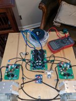
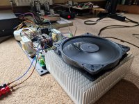
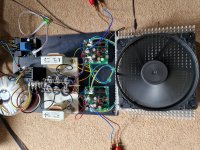
Got my heatsinking sorted. Goodness knows what this Ebay find was originally used for but with a 200mm Noctua fan running at 8.5V there's a ton of very quiet thermal headroom to go to 3A bias. At 1.6A and 20V rails it's only 8deg above ambient. I treated the amp to a custom toroid and got some used chokes for CLC just to see. Sounds sooo much better than the Meanwell switchers I used for test. I would just leave it and enjoy, but got to try CapMx next...
Attachments
- Home
- Amplifiers
- Solid State
- Alpha Nirvana 39w 8ohm Class A Amp