Hello andyr,
I´ve done the layout.
Yes, I'm aware of that, Jan.
Do you´ve seen spades on PC motherboard? Do you know issue using this connectors from PC builders?
No I don't know the issues. (And I don't inspect PC motherboards - just like I don't look under the hood. I just 'drive'. 😀)
My point is simply ... if you use spades for some high current connections ... why not use them for all of them?
There is another issue?!
PS.: MegaFit are 5,7mm pitch instead 4,2mm.
And so? Your PCB needs to be a teeny bit bigger? 😀
Andy
Andy,
simple error - JP is Jean-Paul!
Jan is Jan Hovland, another brilliant man living in WA, US.
Hugh
simple error - JP is Jean-Paul!
Jan is Jan Hovland, another brilliant man living in WA, US.
Hugh
Hi Andy,
I am sorry to hear that you have damaged speakers. You have your JPS' and Jan's mixed up. The Alpha Nirvana layout was done by JPS64, Jan (or Jhofland did the SLB layout). So Jan has nothing to do with the Alpha Nirvana issues you are having.
The Wurth/Molex MiniFit connectors specified are an industrial standard and capapble of reliable connections in high vibration environments. I would take them anyday over soldered flying leads due to the reduction of mechanical strain at the solder joint. Industrial/aersopace/automotive applications use connectors not only for convenience but for better protection of the joint from mechanical strain due to the stress risers at the wire/solder joint interface. I like spade connectors too - they are simple, inexpensive and very compact. That's why I specified them for use in certain locations like the PSU input and optional speaker outputs. But for BJT's amd MOSFETs, I specified Molex Minifit because there are 3 wires that should not ever be mixed up when connecting/re-connecting the actives (it will blow up the MOSFETs/BJTs like a dead short instantly when power is applied). So the connectors help to ensure the proper connections are made and they give convenience of a single connection vs 3. I did not choose to use the Molex Minfit simply because the are "sexy" as you say.
I have successfully used these connectors over many many amps and PSU's, and so have other folks here. We don't seem to have problems. Please show me a closeup photo of one your wire crimps before you insterted it into the shell. If you do it properly, it wil insert and fully seat in the shell and not be able to be pushed out when the shell is inserted into the mating jack that is mounted on the PCB. Here is what a properly crimped wire looks like before it is inserted into the shell (notice how the wings of the crimp wrap smoothly around the wire and clamp it down):
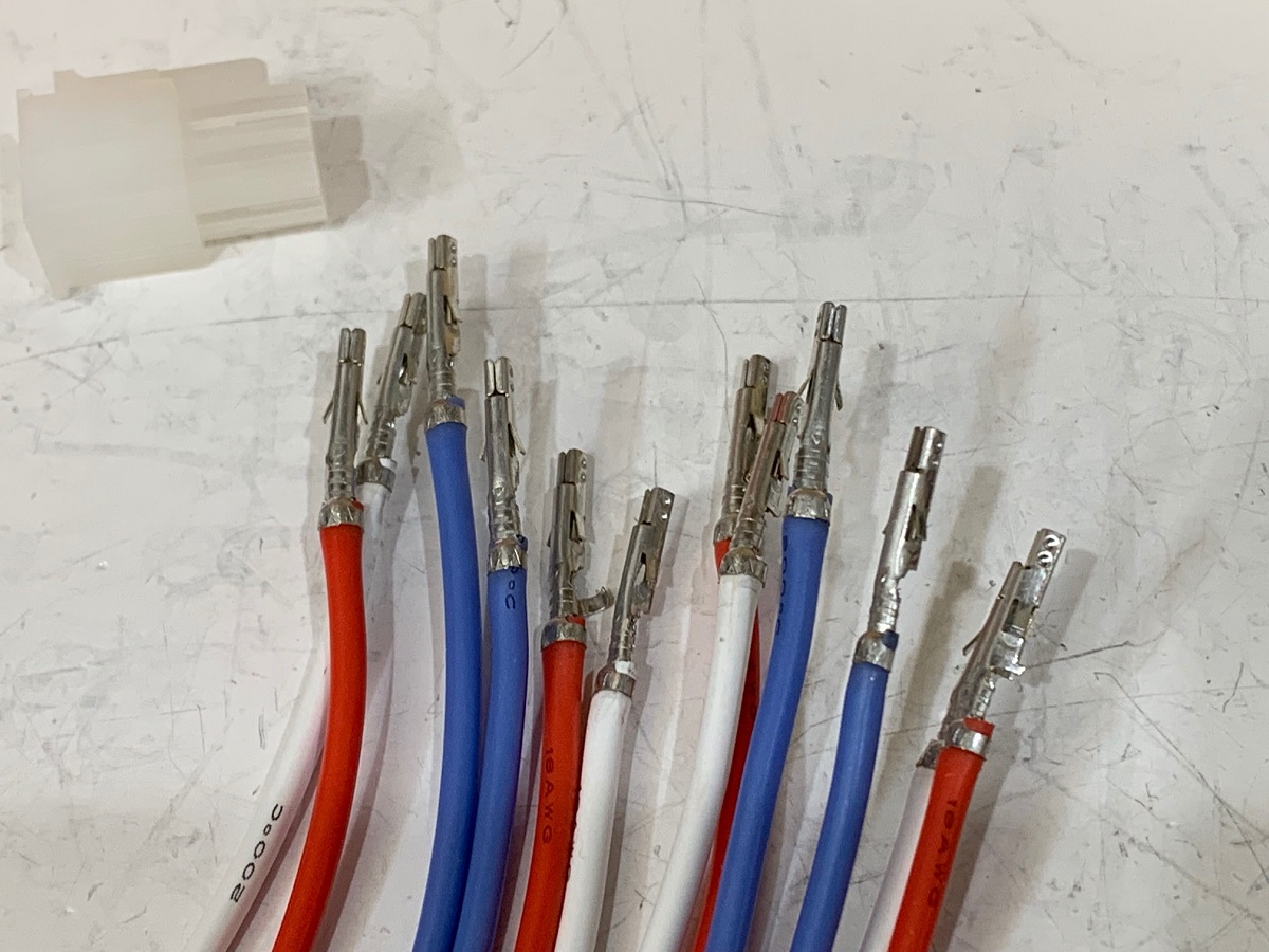
From the photo you posted of your build, I can see that your Molex KK connectors were improperly crimped as they are protruding way out of the shell - ony the wire is visible.
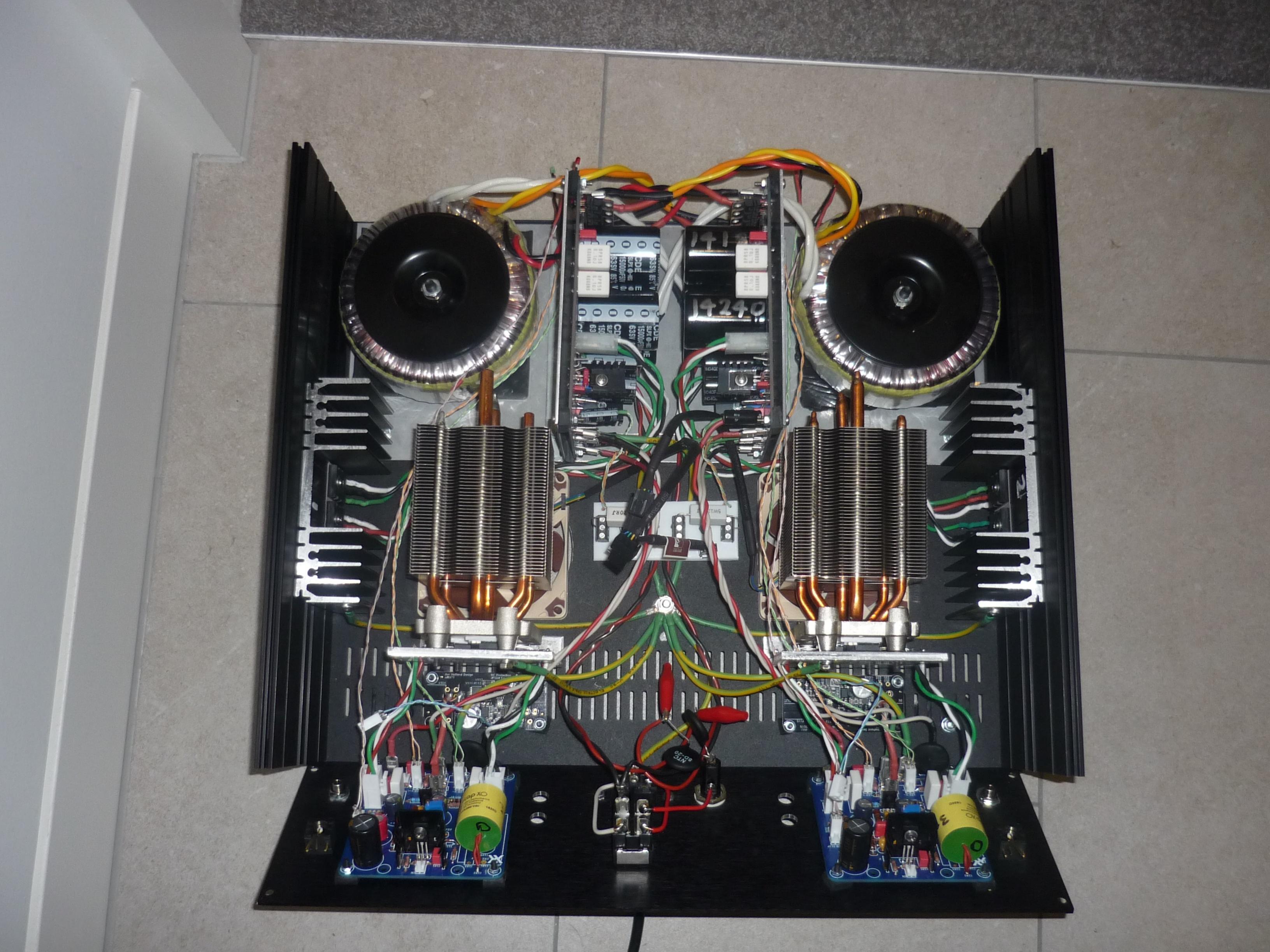
Alhough this is the smaller KK connector, and here is a closeup of the your photo above showing the crimp connectors sticking out of the shell:
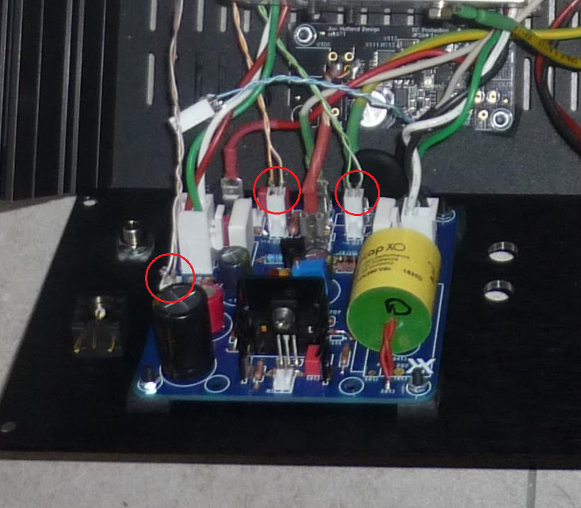
If the same sort of crimping technique was used on the larger Molex Minifit connectors, you probably have an unreliable connection that could come loose with vibration or movement. There is proper technique to making the crimps correctly. It takes a little practice (you will ruin a few crimp connectors in the process) and there are lots of YouTube videos that show how to do it. I even have a quick Howto on it here:
The Alpha Big Boy with Buttah (ABBB) 52w Class A Amp GB
And as others have pointed out, one should always test out a brand new amp using an inexpensive speaker (i.e., a "curb speaker"). It could be a basic $5 full range driver in a cardboard box. If it plays music and your measurement of DC offset is good, then it is safe to move on to connecting your prized $10k speakers. Same is true when connecting a new DIY speaker to an amp, use a cheap amp and not your $5k tube amp - as a member over in the fullrange forum found out when he connected his tube amp to a new speaker he built where the binding posts were shorted together since they both screwed down to a sheet of aluminum on the butyl damping pad in the speaker. Glowing tubes and smole immediately were produced because the spealers presented a 0 ohm load (short) to the amp.
Again, I am sorry for your misfortune and it was a very expensive lesson to learn that the first speaker connected to a new amp should not be your expensive one. You do have the SSR DC protection boards in place, but they won't protect you from square waves or oscillations.
I am sorry to hear that you have damaged speakers. You have your JPS' and Jan's mixed up. The Alpha Nirvana layout was done by JPS64, Jan (or Jhofland did the SLB layout). So Jan has nothing to do with the Alpha Nirvana issues you are having.
The Wurth/Molex MiniFit connectors specified are an industrial standard and capapble of reliable connections in high vibration environments. I would take them anyday over soldered flying leads due to the reduction of mechanical strain at the solder joint. Industrial/aersopace/automotive applications use connectors not only for convenience but for better protection of the joint from mechanical strain due to the stress risers at the wire/solder joint interface. I like spade connectors too - they are simple, inexpensive and very compact. That's why I specified them for use in certain locations like the PSU input and optional speaker outputs. But for BJT's amd MOSFETs, I specified Molex Minifit because there are 3 wires that should not ever be mixed up when connecting/re-connecting the actives (it will blow up the MOSFETs/BJTs like a dead short instantly when power is applied). So the connectors help to ensure the proper connections are made and they give convenience of a single connection vs 3. I did not choose to use the Molex Minfit simply because the are "sexy" as you say.
I have successfully used these connectors over many many amps and PSU's, and so have other folks here. We don't seem to have problems. Please show me a closeup photo of one your wire crimps before you insterted it into the shell. If you do it properly, it wil insert and fully seat in the shell and not be able to be pushed out when the shell is inserted into the mating jack that is mounted on the PCB. Here is what a properly crimped wire looks like before it is inserted into the shell (notice how the wings of the crimp wrap smoothly around the wire and clamp it down):
From the photo you posted of your build, I can see that your Molex KK connectors were improperly crimped as they are protruding way out of the shell - ony the wire is visible.
Alhough this is the smaller KK connector, and here is a closeup of the your photo above showing the crimp connectors sticking out of the shell:
If the same sort of crimping technique was used on the larger Molex Minifit connectors, you probably have an unreliable connection that could come loose with vibration or movement. There is proper technique to making the crimps correctly. It takes a little practice (you will ruin a few crimp connectors in the process) and there are lots of YouTube videos that show how to do it. I even have a quick Howto on it here:
The Alpha Big Boy with Buttah (ABBB) 52w Class A Amp GB
And as others have pointed out, one should always test out a brand new amp using an inexpensive speaker (i.e., a "curb speaker"). It could be a basic $5 full range driver in a cardboard box. If it plays music and your measurement of DC offset is good, then it is safe to move on to connecting your prized $10k speakers. Same is true when connecting a new DIY speaker to an amp, use a cheap amp and not your $5k tube amp - as a member over in the fullrange forum found out when he connected his tube amp to a new speaker he built where the binding posts were shorted together since they both screwed down to a sheet of aluminum on the butyl damping pad in the speaker. Glowing tubes and smole immediately were produced because the spealers presented a 0 ohm load (short) to the amp.
Again, I am sorry for your misfortune and it was a very expensive lesson to learn that the first speaker connected to a new amp should not be your expensive one. You do have the SSR DC protection boards in place, but they won't protect you from square waves or oscillations.
Attachments
Last edited:
"The Wurth/Molex MiniFit connectors specified are an industrial standard and capapble of reliable connections in high vibration environments. I would take them anyday over soldered flying leads due to the reduction of mechanical strain at the solder joint. Industrial/aersopace/automotive applications use connectors not only for convenience but for better protection of the joint from mechanical strain due to the stress risers at the wire/solder joint interface".
Industrial standards are very aware of "economics of manufacture".
I build amplifiers since some 40 years and still prefer solder joints over connectors, but maybe I am an old fashioned stubborn DIY'er. Others are welcome to not agree.
Just something to consider, with Molex connection you have:
1. Molex PCB part soldered to PCB;
2. cable mechanically connected to Molex cable part by crimping;
3. the mechanical (spade) connection.
So three joints instead of just one solder joint.
More can go wrong with the connector isn't it?
An audio amplifier (normally) does not live in a "high vibration environment".
In a well executed solder joint in an amplifier, with well executed wiring, there is no mechanical strain.
There are applications where lead containing solder joints are still used over mechanical connectors; you will find examples in automotive (highly vibrational environment!).
With pads at both sides of the PCB and through hole tinning, you will have a very reliable maintenance free joint (at no extra cost of connectors 🙂). My Rotel not even went that far as it's PCB is one-sided copper...
Attachments
Last edited:
Hi Andy,
I feel your pain..
And I concur with daanve - soldered joints are much more reliable than Molex, or spades for that matter.
There is plenty of bad quality spade connectors on the market too, and they can give troubles too..
Also, soldered wires contribute to smaller PCB.
However - soldered connections are pain in the neck in case of disassembling the amp, servicing, etc..
So there are pros and cons for each solution.
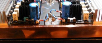
In my build I decided to design my own PCB, and I didn't even look at the BOM 🙂
I don't subscribe to the whole idea of having output transistors connected via long wires, for no reason.
That said, I think AN is a good amp, and well designed, overall.
As usual, builders need to keep their eyes open, be critical, and don't believe everything they read 🙂
I feel your pain..
And I concur with daanve - soldered joints are much more reliable than Molex, or spades for that matter.
There is plenty of bad quality spade connectors on the market too, and they can give troubles too..
Also, soldered wires contribute to smaller PCB.
However - soldered connections are pain in the neck in case of disassembling the amp, servicing, etc..
So there are pros and cons for each solution.
In my build I decided to design my own PCB, and I didn't even look at the BOM 🙂
I don't subscribe to the whole idea of having output transistors connected via long wires, for no reason.
That said, I think AN is a good amp, and well designed, overall.
As usual, builders need to keep their eyes open, be critical, and don't believe everything they read 🙂
Last edited:
😱 🙁 Andy, I feel your pain. So, sorry.
I hope your one mistake (albeit a costly one) doesn't sour you on DIY for good. Love to see you back in the saddle again, soon. Chin up.
I hope your one mistake (albeit a costly one) doesn't sour you on DIY for good. Love to see you back in the saddle again, soon. Chin up.
In my DIY world, I have rarely ever had an amp where I did not have to pull the board out of the chassis/heatsink at least a few times. With the connectors for the power MOSFETs, the step of attaching the outputs to the heatsink and attaching the amp the the chassis are separate operations. Going forward, we now have 4 amps with same Molex connector so that you can leave the MOSFETs and swap out the amp pcb. It can be done in 2 minutes (out and in). Convenience is priceless.
I asked the question why so many people hated spade connectors before in this thread. And same usual answers. Most of which were it’s more reliable and that all connectors are evil. Although I have had the big 16ga soldered leads pull the copper trace up on a board more than one time on me. That’s from all the in’s and out’s during the debug stage of a new amp. How long does it take to pull an amp with outputs fixed to heatsink and then having to replace the output? Fun stuff isn’t it?🙂
For me, I am not going back to mandatory PCB mounted outputs. No thanks.
I know JPS64 often provides optional pads for through hole soldered flying leads. We can do this on the transistor Molex connectors. I suppose you could also just solder the lead through the same pad that the Molex uses.
Last edited:
Hi Andy,
I am sorry to hear that you have damaged speakers. You have your JPS' and Jan's mixed up. The Alpha Nirvana layout was done by JPS64, Jan (or Jhofland did the SLB layout). So Jan has nothing to do with the Alpha Nirvana issues you are having.
The Wurth/Molex MiniFit connectors specified are an industrial standard and capapble of reliable connections in high vibration environments. I would take them anyday over soldered flying leads due to the reduction of mechanical strain at the solder joint. Industrial/aersopace/automotive applications use connectors not only for convenience but for better protection of the joint from mechanical strain due to the stress risers at the wire/solder joint interface. I like spade connectors too - they are simple, inexpensive and very compact. That's why I specified them for use in certain locations like the PSU input and optional speaker outputs. But for BJT's amd MOSFETs, I specified Molex Minifit because there are 3 wires that should not ever be mixed up when connecting/re-connecting the actives (it will blow up the MOSFETs/BJTs like a dead short instantly when power is applied). So the connectors help to ensure the proper connections are made and they give convenience of a single connection vs 3. I did not choose to use the Molex Minfit simply because the are "sexy" as you say.
I have successfully used these connectors over many many amps and PSU's, and so have other folks here. We don't seem to have problems. Please show me a closeup photo of one your wire crimps before you insterted it into the shell. If you do it properly, it wil insert and fully seat in the shell and not be able to be pushed out when the shell is inserted into the mating jack that is mounted on the PCB. Here is what a properly crimped wire looks like before it is inserted into the shell (notice how the wings of the crimp wrap smoothly around the wire and clamp it down):
From the photo you posted of your build, I can see that your Molex KK connectors were improperly crimped as they are protruding way out of the shell - ony the wire is visible.
Alhough this is the smaller KK connector, and here is a closeup of the your photo above showing the crimp connectors sticking out of the shell:
If the same sort of crimping technique was used on the larger Molex Minifit connectors, you probably have an unreliable connection that could come loose with vibration or movement. There is proper technique to making the crimps correctly. It takes a little practice (you will ruin a few crimp connectors in the process) and there are lots of YouTube videos that show how to do it. I even have a quick Howto on it here:
The Alpha Big Boy with Buttah (ABBB) 52w Class A Amp GB
And as others have pointed out, one should always test out a brand new amp using an inexpensive speaker (i.e., a "curb speaker"). It could be a basic $5 full range driver in a cardboard box. If it plays music and your measurement of DC offset is good, then it is safe to move on to connecting your prized $10k speakers. Same is true when connecting a new DIY speaker to an amp, use a cheap amp and not your $5k tube amp - as a member over in the fullrange forum found out when he connected his tube amp to a new speaker he built where the binding posts were shorted together since they both screwed down to a sheet of aluminum on the butyl damping pad in the speaker. Glowing tubes and smole immediately were produced because the spealers presented a 0 ohm load (short) to the amp.
Again, I am sorry for your misfortune and it was a very expensive lesson to learn that the first speaker connected to a new amp should not be your expensive one. You do have the SSR DC protection boards in place, but they won't protect you from square waves or oscillations.
I have to say that I also fell foul to this as well - completely different build unrelated to XRK - spades are reliable because a beginner (like me) with no prior experience in electronics can make a safe and secure connection. Luckily before my second attempt I got a local audio store (Deco Audio, UK) to check out what I had done, they highlighted that my crimps where poor and also that the orientation of insertion of the crimps was wrong. After this hands on guidance I can now make up trouble free connections. Trouble is that this very basic guidance seems to be glossed over on DIYAudio, mainly because a certain level of experience is expected.
Most of people buy spade connectors on ebay....
Majority of these connectors are really bad - made of soft metal, easy to deform; with no grip after few connect/disconnect cycles...
I gave up on spade connectors while ago.
I guess screw terminals are the best.
Majority of these connectors are really bad - made of soft metal, easy to deform; with no grip after few connect/disconnect cycles...
I gave up on spade connectors while ago.
I guess screw terminals are the best.
Last edited:
Spot on - something I also fell foul of. I learnt a lot on my first project! I must say that I like both solutions when done well, just takes a bit of eduction / experience.
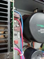
To me it looks like if the wires were soldered to pre used connectors, I would at least used heat shrink to cover them, might even have been a short causing the calamity.😱
..... I must say that I like both solutions when done well, just takes a bit of eduction / experience.
And this would be the way to look at this scenario, nice Stretch 😉
You always have the option to solder the wires directly to the board if your not comfortable using any type of ‘connector’, in the end your the builder. Also, this is diyaudio and there has to be some level of individual responsibility taken.
Myself, I find the connections (Molex, Fastons, etc..) a must-have option. I never build a design and then button it up and never touch it again. I’m always moving internal components, swapping psu’s and generally tweaking. So soldered wires are a no-go for me. But, someone else may have a different opinion. Doesn’t make either side of the debate ‘wrong’.
or you could buy this:
649549516030 Wurth Elektronik | Mouser Deutschland
or this:
POWER CABLE | CC-4420 from be quiet!
JP
649549516030 Wurth Elektronik | Mouser Deutschland
or this:
POWER CABLE | CC-4420 from be quiet!
JP
> Spot on - something I also fell foul of. I learnt a lot on my first project!
Something like this perhaps?
IMO these kind of connectors look very nice and safe. How could I find them in farnell/mouser, any link?
Btw Andy no hard feelings, you made a mistake, but I share your frustration for the burned driver... There were numerous times in the past I wanted to punch my self in similar occasions.. 😀
Andy,
simple error - JP is Jean-Paul!
Jan is Jan Hovland, another brilliant man living in WA, US.
Hugh
Aah, thank you for the very necessary correction, Hugh
Apologies to JP.
Andy
IMO these kind of connectors look very nice and safe. How could I find them in farnell/mouser, any link?
www.digikey.com/product-detail/en/keystone-electronics/8191/36-8191-ND/151565
Blocked
IMO these kind of connectors look very nice and safe. How could I find them in farnell/mouser, any link?
Btw Andy no hard feelings, you made a mistake, but I share your frustration for the burned driver... There were numerous times in the past I wanted to punch my self in similar occasions.. 😀
From the link minek provided, they indeed look very robust!
Andy
To me it looks like if the wires were soldered to pre used connectors, I would at least used heat shrink to cover them, might even have been a short causing the calamity.😱
Not so, Jan - they were new connectors (they come in a packet of 200 - so I had plenty of them! 🙂 ).
And it wasn't a short which caused my problem - it was the socket not making a firm contact with the pin ... and coming loose. 🙁
Andy
- Home
- Amplifiers
- Solid State
- Alpha Nirvana 39w 8ohm Class A Amp