Andy,
Please stop trying to use the incorrect pins in the KK housings!!
I believe your doing more damage to your amps by doing so. Putting shrink wrap around the crimp section that sticks out does nothing to help the incorrect interface between Molex KK header and MiniFit crimps jammed into a KK housing.
Unfortunately, you need to rework ALL your small KK connections with the proper crimps and housing.
Good point, V. 🙂
Thanks,
Andy
+1 or even the fully pre-assembled model from B-Quiet linked earlier or an equivalent part. Proper insertion is also critical, and if there's a doubt, I lean toward pre-assembled connectors. It could save some time and potentially add one more level of peace of mind.
Glad you're sticking with it Andy! 🙂
Glad you're sticking with it Andy! 🙂
Sorry, Jan - I can't picture what you are trying to tell me - re. the Minifit connectors.
Re. the attached pic of a header with 4x un-crimped pin connectors 'dropped into the top' ... which is the correct way for insertion:
1. the 2 fins pointing to the housing lock mechanism at the top (like on the top line)?
2. or the fins pointing out to each side (like on the bottom line)?
Thanks,
Andy
First, please don’t use Minifit on KK, they won’t fit properly and may come loose during use and cause sparks due to intermittency. Plus they can short since exposed.
This video is helpful to show how to crimp the connectors. It does not talk specifically about connector alignment with the shell during the assembly process.
Assembling a Molex Connector - YouTube
Look at the other end of the Molex Minifit shell and you will notice that the holes have a “D” shape. Now look at the pins end on and you will see they have a “D” shape. The two locking barbs that protrude out of the two sides of the D (not the flat opposite of curved part. Those barbs only insert and lock properly when inserted with this orientation (1 in 4 chance you get it right of doing it randomly). If it is not done right, you will notice a lot of mechanical resistance when inserting it into the shell - like it just doesn’t fit. Or it will pull out of the shell with a slight tug, or it pushes out when you insert the mating end that is soldered on the PCB.
On the Molex KK, there is only 1 barb, and it needs to align with the “window” on the shell. So I am not even sure how a Minifit 2 barb connector can go in there. That was an error of omission that the KK crimp terminals were not on the original BOM. It’s one of those things that I (and JPS64 and Vunce) have literally hundreds on hand (like air/water/solder) and we often forget to include it.
It is part number 08550102 and you should get a pack of 100 at least. They are used a lot and very reliable for small signals like audio or smaller power supplies.
I hope that helps.
Sorry to hear about your SSR - it sounds like one of the improperly connectorized KK terminals shorted. Dimly lit green LED means a very low current is passing
and something is damaged. Usually when you see sparks and smell smoke something is burned out.
@rabbitz,
+1
🙂I don't solder wires on amps or speakers as only use mechanical connections except for XLR and RCA leads. I did build a ChipAmp once with soldering the wires and like working with an octopus. With the amp, power supply, transformer all soldered it was a pain. Since then all done with removable modules and mechanical connectors.
Last edited:
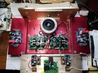
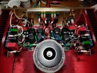
That's a very comprehensive, beautifully crafted amplifier........
Hats off to you, Jan, you are a magician!
Hugh
Hats off to you, Jan, you are a magician!
Hugh
Thanks Hugh,
It's bee a rather long and interesting build process. Just one more little thing to fix in the softstart.
It's bee a rather long and interesting build process. Just one more little thing to fix in the softstart.
The case was purchased on Aliexpress by the client. Gold anodized front and rear panels. Red anodized heatsinks, bottom cover and top cover. I don't happen to have the link to it. A tight fit but I manged to get everything in place.
Case
I like the red heatsinks dif that. I'm not sure about the front and sides, but hey, whatever floats his boat right? 🙂
I like the red heatsinks dif that. I'm not sure about the front and sides, but hey, whatever floats his boat right? 🙂

Hi Adason,
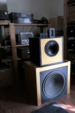
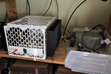
That’s a nice setup you have there. Didn’t know you had so many TT’s. I have a griddle amp and you have what looks like a milk crate amp. 🙂
What is your full range driver? Can’t tell from how it looks - perhaps a dustcap or whizzer cone has been removed?
That’s a nice setup you have there. Didn’t know you had so many TT’s. I have a griddle amp and you have what looks like a milk crate amp. 🙂
What is your full range driver? Can’t tell from how it looks - perhaps a dustcap or whizzer cone has been removed?
Since my AN worked flawlessly for a long time, and I received ideal bridges, I brought it down to main system. Sounds great using fullrange with ribbon on top.
You received ideal bridges? What do you mean by that?

Thanks. I prefer simple crossover, when drivers allow for that. It sounds more natural to me. This is even better performing, yet even simpler crossover speaker, just one cap! Check it out:
Audio Pages: MTM with Vifa 13WH-00-08 and AMT tweeter
Audio Pages: MTM with Vifa 13WH-00-08 and AMT tweeter
I participated in group buy, paid for them and received them.
Ahhh for some reason I was thinking bridge as in wiring up a stereo amp for bridged mono but still couldn’t figure out what you meant by ideal bridges.
I see now, it’s a rectifier bridge design here on DIYA. Had never heard of it till now. Another great circuit to add to my future fully loaded Class A amp build.
Last edited:
Hmm now I see that xrk's SLB PS already incorporates an active bridge like the Ideal Bridge. Nice 🙂
- Home
- Amplifiers
- Solid State
- Alpha Nirvana 39w 8ohm Class A Amp