I have successfully used these connectors over many many amps and PSU's, and so have other folks here. We don't seem to have problems. Please show me a closeup photo of one your wire crimps before you insterted it into the shell. If you do it properly, it wil insert and fully seat in the shell and not be able to be pushed out when the shell is inserted into the mating jack that is mounted on the PCB. Here is what a properly crimped wire looks like before it is inserted into the shell (notice how the wings of the crimp wrap smoothly around the wire and clamp it down):
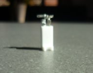
From the photo you posted of your build, I can see that your Molex KK connectors were improperly crimped as they are protruding way out of the shell - only the wire is visible.
Alhough this is the smaller KK connector, and here is a closeup of the your photo above showing the crimp connectors sticking out of the shell:
Hi X,
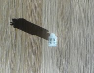
Attached is a photo of a spare 2-pin Molex header - with 2 unused sockets inserted (inserted with different orientations).
These are pushed in as far as they will go - and still stick out the top? (They are the components specified in the AN BoM.)
Andy
Attachments
Last edited:
Andy,
Those crimps look to be for the MiniFit series, you are installing them in the smaller KK series.
The picture is not clear, but I see the wings that crimp around the larger 18awg wire insulation.
If that’s the case, they are on the BOM and are specifically for the MiniFit Jr housing:
https://www.mouser.com/ProductDetail/Molex/39-00-0039?qs=jsoPY5EnoNukaZLXtX9KoA==
Last edited:
Hi Andy,
I like spade connectors too - they are simple, inexpensive and very compact. That's why I specified them for use in certain locations like the PSU input and optional speaker outputs. But for BJT's amd MOSFETs, I specified Molex Minifit because there are 3 wires that should not ever be mixed up when connecting/re-connecting the actives (it will blow up the MOSFETs/BJTs like a dead short instantly when power is applied). So the connectors help to ensure the proper connections are made and they give convenience of a single connection vs 3. I did not choose to use the Molex Minfit simply because the are "sexy" as you say.
Surely, X, there is just as much chance of plugging a mosfet wire into the wrong minifit 'header compartment' as there is plugging a wire onto the wrong spade?
At least, with the spades, there is enough space around them to print '1', '2' & '3' on the PCB - whereas I had to rely upon you to write the correct positions on a picture of the PCB, for the minifit connections.
And as for people who buy their spades from eBay - and get crap as a result ... if they buy from a supplier that can validate its supply chain (like Mouser, Element14 & RS Components, to name just 3), they can be sure of getting the 'real thing'. 🙂
Regards,
Andy
Lots people here on DIY even buy lateral fets from Ebay 🙂
And then there is 10 pages of discussion "why are they fake?", "are you sure they are fake?", "maybe they are real?".
Of course 90% of people gonna buy spades from Ebay, because they're cheap, and as a result they gonna have loose connections.
And then there is 10 pages of discussion "why are they fake?", "are you sure they are fake?", "maybe they are real?".
Of course 90% of people gonna buy spades from Ebay, because they're cheap, and as a result they gonna have loose connections.
Last edited:
Surely, X, there is just as much chance of plugging a mosfet wire into the wrong minifit 'header compartment' as there is plugging a wire onto the wrong spade?
No. You build the wire harness and connector once and check continuity meter against the pins. If it’s correct, it will always be correct thereafter. Not true with three separate spades which can get mixed up each time they come apart. Even I have mixed up positive and negative rail on the main spades to an amp - with disastrous consequences. And I learned my lesson - to always check the polarity after reconnecting the PSU.
I don’t know why your connectors stick out like that - except that maybe you have the wrong crimp connectors for the KK shell. The Molex Minifit connectors are much bigger that the KK connectors.
Last edited:
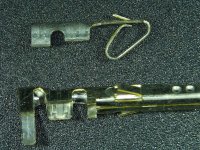
Molex contacts
As Vunce mentioned, the contact pins for the Molex KK series and the minifit series are quite different. I have attached a photo comparing them. The smaller one is what goes into a Molex KK receptacle with the small tine oriented toward the small slot in the receptacle and should be inserted until the tine clicks in place After crimping the minifit contact should still have the two fins sticking out. The contact goes into the receptacle with those fins pointed toward the flat of the D looking at the opposite end of the receptacle as the entry point.
I hope this clarifies how to load them.
Attachments
Perhaps the best answer would be solder the wire into the connector, rather than use a crimper?
Would this give you a 100% perfect connection?
Hugh
Would this give you a 100% perfect connection?
Hugh
Andy,
Those crimps look to be for the MiniFit series, you are installing them in the smaller KK series.
The picture is not clear, but I see the wings that crimp around the larger 18awg wire insulation.
If that’s the case, they are on the BOM and are specifically for the MiniFit Jr housing:
https://www.mouser.com/ProductDetail/Molex/39-00-0039?qs=jsoPY5EnoNukaZLXtX9KoA==
You are correct, V - those sockets are Molex 39-00-0039.
In the Mouser cart for the AN that I printed off back at the start of the year, there are no pin connectors listed for the 2-pin housings (22-23-2021 & 22-01-3027)? Hence I used the 39-00-0039 which actually were specified in the SLB build (Wurth 4-pin connectors / sockets were specified in the AN BoM).
What pin-sockets are supposed to be used with the 2-pin KK series?
Andy
@Andy,
Crimps first Molex KK:
https://www.mouser.com/ProductDetail/Molex/08-50-0114?qs=BLN8Q0P37WapYBZgTV5Zeg==
Hi Hugh,
The crimps will not fit properly in their respective housings unless they are actually crimped.
Soldering is not recommend because it can make the wires rigid and cause interference when plugged into the mating male header.
Last edited:
Perhaps the best answer would be solder the wire into the connector, rather than use a crimper?
Would this give you a 100% perfect connection?
Hugh
The problem I have found with these connectors, Hugh, is not that the wire is not making good contact with the connector, because of a bad crimp - but, rather, the crimped pin-connectors don't make good contact with the pins in the section of the housing that is soldered to the PCB.
Andy
As Vunce mentioned, the contact pins for the Molex KK series and the minifit series are quite different. I have attached a photo comparing them. The smaller one is what goes into a Molex KK receptacle with the small tine oriented toward the small slot in the receptacle and should be inserted until the tine clicks in place After crimping the minifit contact should still have the two fins sticking out. The contact goes into the receptacle with those fins pointed toward the flat of the D looking at the opposite end of the receptacle as the entry point.
I hope this clarifies how to load them.
Thanks for the pic, Jan. I have not seen that top connector before - it was certainly not listed in the BoM that I printed off when I started the build.
I will try out your instruction on how to load the minifit connectors, soon (and see whether I can do it correctly. 🙂 )
Andy
Hi Andy,
It took me a few tries and some bad ones going into the garbage. Personally, I have a harder time with the section of the contact that's supposed to wrap around the wire insulation and I have resorted to trimming a little off and prebending that part so it crimps evenly. The other thing I will note about the KK contact is that trying to use wire a little too big around makes it especially difficult to put into the housing.
Jan
....and I have resorted to trimming a little off and prebending that part so it crimps evenly....
Hi Jan,
I perform the same minor surgery on the ‘wings’ of the Minifit crimps 😉
Last edited:
As Vunce mentioned, the contact pins for the Molex KK series and the minifit series are quite different. I have attached a photo comparing them. The smaller one is what goes into a Molex KK receptacle with the small tine oriented toward the small slot in the receptacle and should be inserted until the tine clicks in place After crimping the minifit contact should still have the two fins sticking out. The contact goes into the receptacle with those fins pointed toward the flat of the D looking at the opposite end of the receptacle as the entry point.
I hope this clarifies how to load them.
Sorry, Jan - I can't picture what you are trying to tell me - re. the Minifit connectors.
Re. the attached pic of a header with 4x un-crimped pin connectors 'dropped into the top' ... which is the correct way for insertion:
1. the 2 fins pointing to the housing lock mechanism at the top (like on the top line)?
2. or the fins pointing out to each side (like on the bottom line)?
Thanks,
Andy
Attachments
Hi rabbitz,
I used the connectors specified in the BoM - they're actually Wurth:
* 710-649004113322 Female, and
* 710-64900421122 Male.
How do the "Molex MegaFit" compare with the above?
Andy
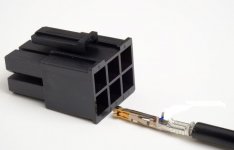
Thanks for that Andy. MegaFit are a beast of a thing and make a great contact on the pin and are good for 600V 26A. I buy the pre crimped wires for these but once in, hard to remove but I found a way.
Molex Mega-Fit wire removal
One issue you can have with crimping is you can press down the locking barb/wing that locks it in the housing which results in the terminal coming out of the housing or rising too far to make contact. I always make sure these are extended before insertion.
I don't solder wires on amps or speakers as only use mechanical connections except for XLR and RCA leads. I did build a ChipAmp once with soldering the wires and like working with an octopus. With the amp, power supply, transformer all soldered it was a pain. Since then all done with removable modules and mechanical connectors.
I've added a pic of the MegaFit and crimp terminal even though it doesn't relate to the one you are using.
Attachments
Last edited:
I've added a pic of the MegaFit and crimp terminal even though it doesn't relate to the one you are using.
Thanks, rabbitz. 🙂
Andy
I've been dealing with the issue which X pointed out, in the amp I'm currently working on - the Minifit pin-connectors poking out of the top of the KK headers (used for:
* DC rail LEDs on the AN board
* clip LED
* power to the SSR boards, and
* signal input).
I slid some red & black heatshrink over the connectors & wires, before 'opening their wings' and pushing the pin-connectors down into the top housing.
My aim was to make sure the tops of the 2 pin-connectors couldn't short, rather than just pushing them apart, as I had previously done.
I would've thought this should've avoided any potential problems ... but, alas, when I then switched on the amp, I saw a flash and smelt some smoke in one channel. So I immediately switched off the amp! 🙁
It would seem the heatshrink wasn't enough to stop a short from happening - which is truly strange, at only 22v.
Luckily - it seems there's no damage to the AN board ... but a bit more checking revealed the SSR board is damaged. So I have just ordered a replacement SSR board. 🙁
Switching on again ... the green LED on the SSR board no longer lights up. However - strangely enough - it's not completely kaput!
Measuring the output at the amp's +ve spkr terminal showed a reading 2000mV in that channel. Whereas when I put the CRO probe on the spkr output terminal on the AN board (the terminal that feeds into the SSR board) ... the amp output is 3500mV - which is the same as the other channel.
So somehow, the power short has:
* stopped the green LED from lighting up
* reduced the output of the SSR board
* but has not blown it entirely! 😕
Anyway, hopefully the replacement SSR board won't take too long to arrive. "Luckily", I can't play music currently ... as I am waiting for the blown ribbon to be repaired. 😀
Andy
Andy,
Please stop trying to use the incorrect pins in the KK housings!!
I believe your doing more damage to your amps by doing so. Putting shrink wrap around the crimp section that sticks out does nothing to help the incorrect interface between Molex KK header and MiniFit crimps jammed into a KK housing.
Unfortunately, you need to rework ALL your small KK connections with the proper crimps and housing.
- Home
- Amplifiers
- Solid State
- Alpha Nirvana 39w 8ohm Class A Amp