Thanks, Hugh.
Oh dear ... so power is actually "ptp output squared divided by 32" - not "rms voltage^2 divided by 4R"! 🙁
Let's use the 38V clipping ptp that I posted above (into 4 ohms); power = 45w. Which agrees with what I measured/calculated in my earlier post.
Again, using the clipping ptp voltage which I got - 38V:
* 19Vp / 4R = 4.75a
* half 4.75a = 2.39a
... which is basically what I have, now - with the 0.15R Source resistors installed. 🙂
Now, I was curious at the relationship between:
* the equation you quoted: power = ptp output ^2 / 32 (where 32 = 8 x 4R)
* vs. the one that I had used: power = rms voltage^2 / 4R.
So I did some noodling around. 🙂
As rms voltage = peak voltage * 1/sq rt of 2
rms voltage^2 = peak voltage^2 / 2.
So, power = peak voltage^2 / (2 x 4R).
And as peak voltage = ptp voltage / 2
power also = ptp voltage^2 / (4 x 2 x 4R).
Andy,
Any amp either clips for lack of current or by hitting the rail for lack of headroom.
Let us design our 4R amp for 39W.
The math tells that you square the peak to peak output and divide by 32.
If we plug in 35Vpp, the watts are 38.3W into 4R.
Oh dear ... so power is actually "ptp output squared divided by 32" - not "rms voltage^2 divided by 4R"! 🙁
Let's use the 38V clipping ptp that I posted above (into 4 ohms); power = 45w. Which agrees with what I measured/calculated in my earlier post.
To be sure you have sufficient current in the AN negative half cycle, divide the negative half cycle peak voltage (17.5Vp) by the load impedance to get peak current - 17.5/4 which gives you 4.37A. Since the peak neg current supported by the AN39 is double the quiescent current (and assuming your impedance is exactly 4R) then your quiescent should be set at 2.19A.
Hugh
Again, using the clipping ptp voltage which I got - 38V:
* 19Vp / 4R = 4.75a
* half 4.75a = 2.39a
... which is basically what I have, now - with the 0.15R Source resistors installed. 🙂
Now, I was curious at the relationship between:
* the equation you quoted: power = ptp output ^2 / 32 (where 32 = 8 x 4R)
* vs. the one that I had used: power = rms voltage^2 / 4R.
So I did some noodling around. 🙂
As rms voltage = peak voltage * 1/sq rt of 2
rms voltage^2 = peak voltage^2 / 2.
So, power = peak voltage^2 / (2 x 4R).
And as peak voltage = ptp voltage / 2
power also = ptp voltage^2 / (4 x 2 x 4R).
That means (2 * up)^2 / (8 * R_load) ---> (4/8) * up^2 * (1/R_load) ---> (1/2) * W_peak equals RMS-Power for sinusoidal time functions and (constanc) static loads R+/-j0.The math tells that you square the peak to peak output and divide by 32.
The definition for the class A operating case is now very simple:
as long as the (peak) load current is less than the DC quiescent current (through the active power transistor), we speak of class A in the classifications.
That is the simple view.
#
The classifications A, B, (AB), C, D have nothing to do with the basic performance or even the sonic pleasure.
Among other things, the power supply unit must be able to cover the current requirements of the load in all (specified) operating cases in the first instance and the amp must not prevent this.
Because our connected load is not an ohmic resistor ... but this topic has certainly been discussed countless times in this forum - other technical issues are more important in development than, for example, a kind of fetish or nimbus!
##
I don't know the whole thread, nor the amplifier of this thread, I just had a quick look at the first schematic ... but I assume that this nifty little amp is flawless.
Class issues should really be dealt with elsewhere.
Bye,
HBt.
fine 🙂Again, using the clipping ptp voltage which I got - 38V:
* 19Vp / 4R = 4.75a
* half 4.75a = 2.39a
... which is basically what I have, now - with the 0.15R Source resistors installed.
One last time for illustration:
Amplitude up=19V and ip=4.75A Power = Voltage * Current ---> 90.25W_peak into 4 V/A +/-j0
for sine or cosine ---> 45.125W as RMS viewed' quals the heat (as energy) under DC conditions.
Is the standing current greater the forced current by the load?
No, so now we have to soften the definition, or for PP' from a different perspective (talk ourselves out of the issue) ... it doesn't matter!
1444 V^2 / 32 V/A is also 45.125 VA !
Light in the dark (?),
HBt.
Addendum:
If a transistor involved in a cycle is switched off, we speak of class B at this time; if this is not the case, the operation is AB or A ...
The rest is anyone's guess - but is that important?
If a transistor involved in a cycle is switched off, we speak of class B at this time; if this is not the case, the operation is AB or A ...
The rest is anyone's guess - but is that important?
I don't want to offend anyone here, that up front, "andyr" kind of dragged me into this thread.
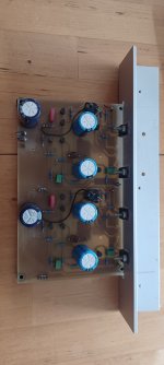
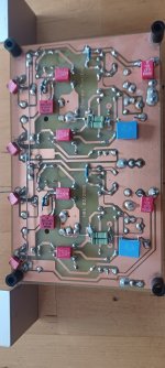
I like the circuit, but I've known the circuit principle used for at least 30 years and it's nothing special to me - I'll put the proof in the appendix, a test circuit for my daughters from 2005, I probably called it Aleph mini or something like that, it's all old hat.
But, to the class questions:
You have to plot the time course of the current functions, oscilloscope them - I_drain(t)_M1 and I_drain(t)_M2 ! Then you know what is going on.
Attachments
I’ll make a note that 2.2A quiescent current is needed for 4ohm variant in post 1.

I’ll make a note that 2.2A quiescent current is needed for 4ohm variant in post 1.
I suggest all that is needed is to change R141 & R142 (R15 & R16 in Hugh's 4R schematic) to 0.15R, instead of 0.12R.
I don't think reducing the bias current from the original 3a (with 0.12R) degrades the SQ in any way ... but maybe 3a bias current improves the AN4R's ability to drive lower-impedance loads? Like 2 ohms?
First about this:Nonsense is when people get emotionally irritated by disagreement about technical issues. Shall we ban unpleasant facts? Lets speak frankly and openly, as usual.
There are some other changes that should be done regarding classification.
Fortunately, these changes do not have any impact whatsoever on consensus about extraordinary sonic qualities of this amplifier,
But this is not the only change that should be made because the shift from 1.7A to 2.2A has direct impact on the valute of efficiency which now drops to about 33%.I’ll make a note that 2.2A quiescent current is needed for 4ohm variant in post 1.
There are some other changes that should be done regarding classification.
Fortunately, these changes do not have any impact whatsoever on consensus about extraordinary sonic qualities of this amplifier,
Last edited:
I try very hard to simplify my explanations but with reductio ad absurdum you inevitably gloss over some of the peripheral, less important issues around the circuit.
OTOH, I have been in this forum long enough to realise that many technologists get hung up on some of the smaller issues, like capacitor choices, inductive sensing resistors, and resistor ratioes on bootstraps, etc. I really try to avoid this stuff; already I have been pilloried by some of the most august scientific minds in the forum, and with ordinary health I try to avoid it since no-one likes to be seen as a fool.
And of course, there are always those who love to have the last word....... but I have been married for 40 years so I'm fine with that.
Silvio, you are absolutely correct about the reduced efficiency. It's best at 8R loading, no question....
HD
I try very hard to simplify my explanations but with reductio ad absurdum you inevitably gloss over some of the peripheral, less important issues around the circuit.
I wouldn't worry about it, Hugh. I would suspect most of us who have built the AN are only interested in how wonderful it sounds - and couldn't give a toss about arcane technical details.
OTOH, I have been in this forum long enough to realise that many technologists get hung up on some of the smaller issues, like capacitor choices, inductive sensing resistors, and resistor ratios on bootstraps, etc.
Let them have their jollies ... and don't feed the dingos! 😀
Silvio, you are absolutely correct about the reduced efficiency. It's best at 8R loading, no question....
If so - shirley it would be even more efficient at 16R loading! Yet who would want to build an AN16? 😵
Me, I built the AN4R to power the 2ohm ribbons on my Maggies. Which it did. "Efficiency" was entirely absent from my decision-making process.
So thank you for a. designing the AN8R, Hugh - and then extending it to drive 4R spkrs. 👍

This thread has degenerated into one of trading insults. Some of you will find you can no longer post here for an extended period. Others will find their posts have been deleted.
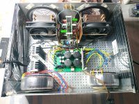
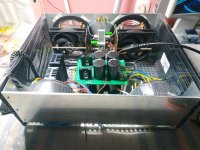
Nikos@ I like your construction 👍
The heat issue is a tricky one. Here in Spain, unfortunately, there are also episodes of very hot weather.
Luckily, I have been able to mount an air conditioner at home. The problem is that I can't finish mounting the Alpha Nirvana, nor some speakers that I'm making myself, the air conditioning has taken all my budget...what a rage 😤
I hope to clean up my economy soon.
Regards
@jim
Many thanks i support England but.....Never mind next time .very good effort.
@ Ιsmael
Congratulations for the cup....I have two air conditioners a Mitsubishi Heavy of 18,000 btu and one Toyotomi 9000 btu in my room.... But in the winter I suffered from sinusitis for the first time....so I put it on with fear.......
Karucho,
As one who suffers through >40C summers in Australia, I can confirm we too must live with air conditioning and could not live without it.
So, Climate #1, Alpha Nirvana #2!!
Your summer will over in a couple of months however, good luck with the build!
Ciao,
Hugh
As one who suffers through >40C summers in Australia, I can confirm we too must live with air conditioning and could not live without it.
So, Climate #1, Alpha Nirvana #2!!
Your summer will over in a couple of months however, good luck with the build!
Ciao,
Hugh
I'm trying to finish the box and the second channel of the amp.....but the heat wave is holding me back. Tooooo hooot 36-43C this month.
In contrast, we are having some severely chill weather here - so my AN4Rs are making the temperature in my listening room a lot more friendly. 🙂
- Home
- Amplifiers
- Solid State
- Alpha Nirvana 39w 8ohm Class A Amp