Thank you Nikos - A very well built AN.
BMM,
The 4700p cap should be thru hole but could be a SMD. The 11p is a compensator and shouldbe silver mica for best SQ. These are mandatory caps.
Hugh
BMM,
The 4700p cap should be thru hole but could be a SMD. The 11p is a compensator and shouldbe silver mica for best SQ. These are mandatory caps.
Hugh

Thanks Andy.Just something you may not be aware of regarding powering 12v fans from the amp's PS (in my case, SLBs).
The first build of my AN4Rs had the output devices of each channel bolted to a CPU cooler, with a fan blowing through the cooler fins. I used a wirewound resistor to drop the +21v DC rail to about 10v.
Cooling-wise ... everything worked well - however, I found that the fan produced a ripple on the +DC supply (which wasn't there on the -21v DC rail ... which didn't have a fan connected to it).
So I had to add a 'pi filter' to the DC feed to the fan - this removed the ripple!
i saw this noise -ripple from the fan at my osc.... you have make a good point.
Can you show us the pi filter?
its a fix filter ? or can you give us the values cap- res of this?
is that filter inside the red circle?
Attachments
Last edited:
Hi BMM.Hello NIkos,
I’m going to be running a 12v fan. I assume You using the psu to run them?
Thnx,
BMM
I use a general small pack psu ....nothing special just for the tests ...usually i use the main amp PSU to take voltage from the caps....
but now Andy says about the ripple- noise from the fan that noise confirmed also by me at the test with osc when the fan its active.
Last edited:
Thanks Andy.
i saw this noise -ripple from the fan at my osc.... you have make a good point.
Can you show us the pi filter?
its a fix filter ? or can you give us the values cap- res of this?
is that filter inside the red circle?
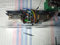
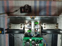
No, that's the original setup (with just the resistor to lower the voltage) before I discovered the ripple.
Here's the voltage resistor terminals ... plus the Pi filter:
The spade connectors go to the SLB; the fan connectors plug onto the white pin-connectors at the bottom of the board. The teflon board is about 90mm square.
I can send it to you, if you'd like. (Just reimburse the postage.)
Any of you guys compare the sound
on Nirvana listening to bias change
From 2.6ma to say 2.2ma to my ears
This thing is more linear when dropping back closer to 2ma,
Sounds to my ear that 2.6ma bias is pushing it right to the edge imho
Any thoughts?
Scott
on Nirvana listening to bias change
From 2.6ma to say 2.2ma to my ears
This thing is more linear when dropping back closer to 2ma,
Sounds to my ear that 2.6ma bias is pushing it right to the edge imho
Any thoughts?
Scott
Any of you guys compare the sound
on Nirvana listening to bias change
From 2.6ma to say 2.2ma to my ears
This thing is more linear when dropping back closer to 2ma,
I presume (like jaques) ... you mean amps - not milliamps? 😵
Sounds to my ear that 2.6ma bias is pushing it right to the edge imho
Any thoughts?
Surely it depends which version of the circuit you are altering the bias on:
- the 8R version (bias 1.7a)
- or the 4R version (bias 3a)?
I think bigaudioscotto talking about LTP bias....2.6ma or 2.0 -2.2 ma.
Aah, OK. 👍
I wouldn't know how it can be changed! 🙁
Yes it can be .....but when approach to 2.6ma the dc offset goes to 15-20mv , for zero offset about 2.24-2.26ma with 5k and 500Ω pot for 4R version.
Yes it can be .....but when approach to 2.6ma the dc offset goes to 15-20mv , for zero offset about 2.24-2.26ma with 5k and 500Ω pot for 4R version.
Aaah, OK - the offset adjustment. Thanks. 👍
I would've thought that adjustment is used for getting the DC offset as low as possible.
The real change to the amp's sound is probably what you set the bias for the output devices to!
You and i we staying at 3.1A(0.11Ω) or 2.8A(0.15Ω) and many others for 4R version.... toooooo HOOOOOT my friend too hot.....hahaha.The real change to the amp's sound is probably what you set the bias for the output devices to
Yes I was talking about LTP bias.I think bigaudioscotto talking about LTP bias....2.6ma or 2.0 -2.2 ma.
Hi, it is curious, in some circuit it is reflected at 1.90 mA.
Greetings

Greetings
Yeah I think everyone should use a 1k pot at R113 and play with the bias from 2ma
To 2.6ma to see the changes in sound on your rig,
It does seem a little more relaxed sounding and not pushed so hard when backing down on the bias and also will run a little cooler as well.
To 2.6ma to see the changes in sound on your rig,
It does seem a little more relaxed sounding and not pushed so hard when backing down on the bias and also will run a little cooler as well.
Yes .....but it use 2N5401C and not KSA992.....i use 2N5401C and acting different total ....more dc offset with same values 5k and 500Ω pot maybe want's other values resistor and pot.
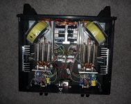
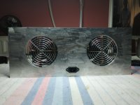
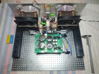
Hi my friends.
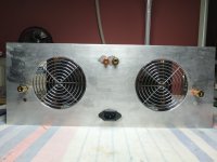
Small steps about the DIY box.
Finally dimensions 43.5 x 35 x16.8 cm with a lot free air inside.Will see how acting finally when i put the cover about the temperatures active fan..... when finished.
Small steps about the DIY box.
Finally dimensions 43.5 x 35 x16.8 cm with a lot free air inside.Will see how acting finally when i put the cover about the temperatures active fan..... when finished.
Attachments
- Home
- Amplifiers
- Solid State
- Alpha Nirvana 39w 8ohm Class A Amp