Anand,
I would just at least a 100V mosfet, and I did not mention earlier but I found that the best devices are Polar, rather than Trench mosfets.
I'm surprised mosfets are getting hard to get; I favoured FQA40N25 and FQA36P15, both rated to 280W from Fairchild in the past.
I tried some other Trench mosfets and found they do not like linear operation; they are designed for on or off, nothing in between.
HD

Andyr,
Thanks, I’m going to make an order digikey. I am trying to get all the parts from one place so I can limit the shipping.
Thanks, I’m going to make an order digikey. I am trying to get all the parts from one place so I can limit the shipping.
I have started on my Nirvana build. Just wanted to say a quick thanks to the folks who have assisted me so far in selecting parts.
I am over the moon to be building a Hugh Dean Class A design! I've been through this entire thread 5-6 times now.
My long lead item right now is the transformers from Toroidy. I should have ordered them sooner. My Nirvana boards are about 90% stuffed, as are my Smooth Like Butta' power supply boards.
Again, thanks to all who have provided information, whether directly or in this thread.
My long lead item right now is the transformers from Toroidy. I should have ordered them sooner. My Nirvana boards are about 90% stuffed, as are my Smooth Like Butta' power supply boards.
That's a shame. 🙁
But seriously ... are there no toroid mfrs in the US? 😵
Antek Transformer is very common in the States and can be received within days of placing an order. But, no custom winding options like Toroidy. Having used several types of both brands I’d give the edge to Toroidy for manufacturing quality.
That's sad to hear, Vunce. Here in Oz we have (for toroids):
* Tortech
* and Harbuch.
Both make custom (as well as standard) power toroids and are high quality.
And we have a lot of others who make EI transformers.
Antek was definitely an option, but I had used them on the 2 previous amps I built. They are inexpensive and Antek has great customer service.
After seeing the Toroidy in Anand's build and hearing his opinion, I wanted to give Toroidy a try. Much more expensive, hopefully worth it.
I am a few years late to the Nirvana party but hoping to catch up!
After seeing the Toroidy in Anand's build and hearing his opinion, I wanted to give Toroidy a try. Much more expensive, hopefully worth it.
I am a few years late to the Nirvana party but hoping to catch up!
What's so special about these Toroidy transformers apart from the beautiful presentation and shielding....do they sound better?? I would like to hear his opinion....After seeing the Toroidy in Anand's build and hearing his opinion
Hello,
R113 says tbd. What value is this one? what wattage should R124 and r126 be? On the h121 led. On the board where it says led v- and led v+. They go there with the positive and negative legs fallowing the - and + respectively?
Thnx,
BMM
R113 says tbd. What value is this one? what wattage should R124 and r126 be? On the h121 led. On the board where it says led v- and led v+. They go there with the positive and negative legs fallowing the - and + respectively?
Thnx,
BMM
Here is the schematic I worked with. It‘s much easier to answer questions since I haven’t memorized part numbers.
If you look at the Mouser BOM link on the 1st page of the thread, and click on the resistors R124 and R126 you’ll see they are spec’d for 0.5 watts. That’s a minimum number. You can place a 1 watt size there as long as it fits too.
R113 is a potentiometer (try 500 ohms or 1K ohms). You need to adjust it for about 2 mA across R111 or R112 while also observing DC offset on the amplifier outputs. I believe I wrote a cliff notes guide and the link is on the 1st page of this thread. Here is the link. For the H121 LED I just placed it directly on the board, anode is positive and cathode is negative (there is a section that states ‘LED CLIP’). You have the option of also placing it on your front panel with twisted wire leads coming back to the board if you want it as a visual indicator of when the amplifier is clipping. BTW, V121, H121 and V122 are optional. They are not needed for the function of the amplifier. It Is just a cool visual tweak that Hugh provided.
Best,
Anand.
Last edited:
Thank you Anand, you have been very instructive to builders and I am most grateful.
I concur with all your directions!
Hugh (suffering with nasty flu picked up from the petri dish of childminding of his grandchildren)
I concur with all your directions!
Hugh (suffering with nasty flu picked up from the petri dish of childminding of his grandchildren)
Anand,
Ran into some more confusion today. To be clear, it is either or on c115, c114? Is this the same with c125/0 and c126/0? c124 and c1240. What to do here? these 2 caps go here, correct? What have people been doing? C102-105, I don’t know much about audio caps. Will one big wima cap be good? Or do you have a recommendation?
Thnx,
BMM
Anand,
Ran into some more confusion today. To be clear, it is either or on c115, c114? Is this the same with c125/0 and c126/0? c124 and c1240. What to do here? these 2 caps go here, correct? What have people been doing? C102-105, I don’t know much about audio caps. Will one big wima cap be good? Or do you have a recommendation?
Thnx,
BMM
Once again, please read my cliff notes. It is post 2140 if the link doesn’t work.
Best,
Anand.
Hugh,
I think I figured it out. My confusion was around 125/0 122/0. Whether or not the caps were there to be paralleled or they are optional? From what I gather they are smd optional with thru hole? Ive never had this on an pcb before. So, I used the thru hole options. I am done with the boards and I will start laying out the boards in the chassis.
Thank you for your concern,
BMM
Mr HughBMM/Nikos,
How are you getting along? Any issues we need to help you with?
Hugh
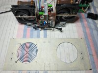
My amplifier has been ready for a long time, I don't have any operational problems. Also the cooling in this way for 3.1A is extremely good. 44 C active heatsinks ,52-54 C on body case, of mosfets, temp air 20-21 C . I am preparing the back side of the box where the heat from the active heatsinks will escape....Thank you also for your concern.
Attachments
Last edited:
Hello NIkos,
I’m going to be running a 12v fan. I assume You using the psu to run them?
Thnx,
BMM
I’m going to be running a 12v fan. I assume You using the psu to run them?
Thnx,
BMM
Hello NIkos,
I’m going to be running a 12v fan. I assume You using the psu to run them?
Thnx,
BMM
Just something you may not be aware of regarding powering 12v fans from the amp's PS (in my case, SLBs).
The first build of my AN4Rs had the output devices of each channel bolted to a CPU cooler, with a fan blowing through the cooler fins. I used a wirewound resistor to drop the +21v DC rail to about 10v.
Cooling-wise ... everything worked well - however, I found that the fan produced a ripple on the +DC supply (which wasn't there on the -21v DC rail ... which didn't have a fan connected to it).
So I had to add a 'pi filter' to the DC feed to the fan - this removed the ripple! 👍
- Home
- Amplifiers
- Solid State
- Alpha Nirvana 39w 8ohm Class A Amp