
Andy,I use a Peak Atlas DCA75; this can measure various things, including:
* whether a semiconductor (diode, transistor, jfet, fet LED) is working or dud.
* Hfe for transistors
* Idss for jfets
* voltage drop for diodes.
It's the first time I can't measure Hfe with my DMM and I don't understand the reason. I have checked many BC550-560s. Is that happening because it's an epitaxial bjt? I do not have an atlas DCA75. How am I supposed to match the goddamn transistors?
Please some help !!!!
Andy,
It's the first time I can't measure Hfe with my DMM and I don't understand the reason. I have checked many BC550-560s. Is that happening because it's an epitaxial bjt? I do not have an atlas DCA75. How am I supposed to match the goddamn transistors?
Please some help !!!!
If you buy the right tool for the job ... you can do it! 🙂
So I suggest it is time for you buy an Atlas DCA75. It's essential to match that pair of transistors. 😱

Andy,
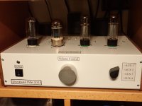
I don't think that I need to spend 200 euros on a transistor tester as my big love is tubes!!!! My previous two class A amplifiers had BC 550 - 560 bjt and there was no problem matching them with my DMM. This is the last SS amplifier ( I have already a Cary SLA70 2X35W class A and an Audio Note kit2 class A 2x18W) I will build and then my atlas would rest in peace forever. I had built an elektor transistor matcher a long time ago and I will have to look for it somewhere in my lab. Thank you very much for your concern and suggestion. Last week I finished building P.Millett Low mu tube preamp and it sounds superb. Take a look.
I don't think that I need to spend 200 euros on a transistor tester as my big love is tubes!!!! My previous two class A amplifiers had BC 550 - 560 bjt and there was no problem matching them with my DMM. This is the last SS amplifier ( I have already a Cary SLA70 2X35W class A and an Audio Note kit2 class A 2x18W) I will build and then my atlas would rest in peace forever. I had built an elektor transistor matcher a long time ago and I will have to look for it somewhere in my lab. Thank you very much for your concern and suggestion. Last week I finished building P.Millett Low mu tube preamp and it sounds superb. Take a look.
Attachments
Maybe others can tell you what they used to do this important matching?
(I've told you how I did it. I also bought 100 of these transistors, so I would have enough of them to get a very close match. 😱 )
And, sorry, the P.Millett Low mu tube preamp is of no interest to me - as my heavily digitally-oriented system doesn't use a 'preamp'. (I use a 4-way digital source selector instead.)
Andy,
Thanks a lot for your suggestions again.
I will surely find a way to match the transistors and I hope my offset will be at proper values.
Thanks a lot for your suggestions again.
I will surely find a way to match the transistors and I hope my offset will be at proper values.
@metanastis you can try this tester and should work with most of the transistors if you do not want to spend more -
ESR Meter Transistor Tester Diode Triode Capacitance SCR Inductance Tester
https://a.aliexpress.com/_mOzaick
ESR Meter Transistor Tester Diode Triode Capacitance SCR Inductance Tester
https://a.aliexpress.com/_mOzaick
Hi Metanastis,
To help you with matching, first concentrate on the Vbe measurement for a current used on the amplifier. Beta can then be tested easily on the DVM, but Vbe is pivotal on a long tailed pair. I have done a small schematic using a simple 9V battery to permit matching for npn and pnp transistors (independently of course, you don't need to match npn and pnp, only within the same gender) below. This is ONLY for measuring Vbe, NOT hfe. I have found Vbe is more important for amps than matching for beta.
Cheers, Hugh
Hugh,
Thank you very much for your concern. I will make the circuit on an empty board.
As I can recall I had built a similar project taken from Elektor magazine ( transistor match maker). I will definitely find it somewhere in my lab.
Do you think it can help? It was in a little construction box with a +-9vdc power supply and clip leads. It had helped me match the BC550 and BC560 at my first class A amp- Elektor AXL amp- many years ago.
Thank you very much once again.
Hi, I have a question about the input impedance of the 20w version of the "Alpha Nirvana".
The thing is that I don't know if the input impedance is equal to R1+R2=222,5k, or to R1+R2//R3=22,5k.
Thanks in advance

The thing is that I don't know if the input impedance is equal to R1+R2=222,5k, or to R1+R2//R3=22,5k.
Thanks in advance
Happy New Year everyone, best wishes to all,
I have a quick question on chassis/fan construction. When looking at the attached pic of a metal base with 90mm cutouts for the fans I will use, is 1 or 2 a better construction method:
1. Install with fan on the underside of the metal base with the cpu heatsink on topside of metal base, or,
2. Install the fan and cpu heatsink, both on the top side of the metal base.
I am no air flow genius, and was wondering if anyone has knowledge on which scenario above would be more efficient for supplying air to the fan. Maybe no difference?
Personally, I like the fan and cpu heatsink on the topside as the heatsink would be 1" closer to the vents in the top of the enclosure once built.
Thanks for your comments,
MM
Happy New Year everyone, best wishes to all,
I have a quick question on chassis/fan construction. When looking at the attached pic of a metal base with 90mm cutouts for the fans I will use, is 1 or 2 a better construction method:
1. Install with fan on the underside of the metal base with the cpu heatsink on topside of metal base, or,
2. Install the fan and cpu heatsink, both on the top side of the metal base.
I am no air flow genius, and was wondering if anyone has knowledge on which scenario above would be more efficient for supplying air to the fan. Maybe no difference?
Personally, I like the fan and cpu heatsink on the topside as the heatsink would be 1" closer to the vents in the top of the enclosure once built.
Thanks for your comments,
MM
View attachment 1252364
I used #2 in my first AN build. (Except the fans were blowing onto CPU coolers, not conventional heatsinks). The only issue is ... you have to use spacers, to lift the heatsinks, say, 6mm above the fans.
But I have to ask ... why aren't you using a case which has finned-heatsink sides?
For the cpu cooler to work best, the fan must be attached to it. Think of it as one module, not a separate fan blowing in the direction of the cpu cooler.
For the cpu cooler to work best, the fan must be attached to it. Think of it as one module, not a separate fan blowing in the direction of the cpu cooler.
Aah, OK - thanks, V. I didn't know the best result was from a "one-module" construction. 👍
Wow, thanks for the quick replies. Please see the pic below, should clear up any questions asked.
For the fan located below the HS on the left side of the pic, the amp base would have to be elevated to 2"-3" to provide adequate air supply ( in my estimation ). The HS will be attached tightly to the base (and the fan below the base). I am not sure if this may provide some extra heatsinking (WAG on my part)😉
The fan on the right side of the pic, shows the HS mounted on top of the fan on top side of metal base. The amp base should be able to be lower and still have adequate room for air supply to the fans. This would also raise the heat sink closer to the top of the vented enclosure for more efficient air removal.
The one on the right side is the one I am favoring. The enclosure part is from a gutted 5 channel receiver with vented sides and top. Top of enclosure is about 150mm high. I will be fitting a new front and back plate.
MM
Hey guys has anyone completed this 4R version ?
also does it need any parts revisions?
Thanks

also does it need any parts revisions?
Thanks
bigaudioscotto
This is the correct version. The pcb is not tested and there aren't smd parts and molex connectors. You can easily see all the parts' connections. Check it by yourself to the original schematic diagram. The gerbers are available for everyone. XRK pcb is really great, although I hate smd and molex😆!!!! I will give it a try in the future.Metanastis,
Thanks for the feedback.
Could you PM me the Gerber file?
Also I would probably add thru hole solder pads to top
side as well.
Thanks
Scott
Thanks for the feedback.
Could you PM me the Gerber file?
Also I would probably add thru hole solder pads to top
side as well.
Thanks
Scott
- Home
- Amplifiers
- Solid State
- Alpha Nirvana 39w 8ohm Class A Amp