Anand
Thanks for the input,
Right now if I measure from edge to center of the screw mount I am at 67mm from side and 70mm from bottom hopefully that will work?
Scott
Thanks for the input,
Right now if I measure from edge to center of the screw mount I am at 67mm from side and 70mm from bottom hopefully that will work?
Scott

Vunce,
Well now you have me thinking I need to go 5U 400mm man I just hate dropping $400 For that .
Scott
Well now you have me thinking I need to go 5U 400mm man I just hate dropping $400 For that .
Scott
You can always decrease your dissipation by increasing your current source resistor values. You can also decrease your rail voltages. Both will decrease dissipation but will also decrease power. I know 0.25 ohms (for R141, R142) and +/- 24V works well.
Choices. Choices.
See if 5U/300 works for you first…
Best,
Anand.
Choices. Choices.
See if 5U/300 works for you first…
Best,
Anand.
Yeah, I hear Ya! A proper chassis is by far the single biggest cost for class A builds.
Continue on your path, but modify.
Get one channel mounted on the 300mm heatsink and fire it up. See how hot it gets, then make your decision.
Anand’s strategy would work well also😉
Continue on your path, but modify.
Get one channel mounted on the 300mm heatsink and fire it up. See how hot it gets, then make your decision.
Anand’s strategy would work well also😉
I could get another pair of 5U 300mm
Connect them giving a total of 600mm
Depth each side that would stay cool
I imagine but then I would have to fabricate my own bottom and top.
Scott
Connect them giving a total of 600mm
Depth each side that would stay cool
I imagine but then I would have to fabricate my own bottom and top.
Scott
Anand,
We're did you find the 0.25 ohm resistor for R141 and R142 that is an obscure value
For sure! I have some 0.27 ohm koa bpr I could use.
Thanks
Scott
We're did you find the 0.25 ohm resistor for R141 and R142 that is an obscure value
For sure! I have some 0.27 ohm koa bpr I could use.
Thanks
Scott
It’s not an obscure value.Actually quite common. Just not available as koa bpr brand from mouser since they don’t stock it.
If you look at the original schematics you will see that 3W resistors can also be used. Just try to find non inductive ones. Now your search expands. Try Mouser, Digikey, etc…check dimensions, etc…
0.27 ohms might be possible but be aware bias will drop a little more. Probably about 1.35A instead of 1.7A. That will affect 4 ohm loads. Up to you.
Best,
Anand.
Anand,
Got it thanks.
I guess the easier way would be just running 20v toroids instead of the 22v
Pair I have now running a pair of SLB
Supplies that would give me around 26v
vs 28.5 that I am now getting,
What do you think?
Scott
Got it thanks.
I guess the easier way would be just running 20v toroids instead of the 22v
Pair I have now running a pair of SLB
Supplies that would give me around 26v
vs 28.5 that I am now getting,
What do you think?
Scott
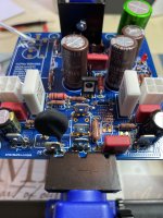
On the image in the circle is that the
Connections for speaker + and -
And which is which?
Or are those both + connectors and the speaker -
Can run to the SLB ground?
Scott


Connections for speaker + and -
And which is which?
Or are those both + connectors and the speaker -
Can run to the SLB ground?
Scott
Within the black circle you have drawn:
Top is speaker output (+)
Bottom is speaker output (-)
Use your DMM and trace the circuit, it will verify when you check with the schematics on the 1st post. The speaker output (+) should be connected to one side of each of the current source resistors.
Also see sledwards' excellent build.
Best,
Anand.
Anand,
I am going to use the faston connectors Not using the 4 pin connector At speaker output just using those faston connectors above and below were the 4 pin connector would go right? In image below
Scott
I am going to use the faston connectors Not using the 4 pin connector At speaker output just using those faston connectors above and below were the 4 pin connector would go right? In image below
Scott
Attachments
Last edited:
- Home
- Amplifiers
- Solid State
- Alpha Nirvana 39w 8ohm Class A Amp