Hey guys
Well I tried firing one Nirvana board up
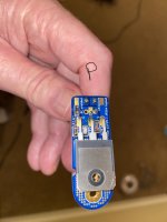
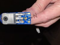
And the N channel is not working not sure what I could have missed I have the N channel snubber board diode with line toward bolt end and P channel with diode line toward the connector pins side?
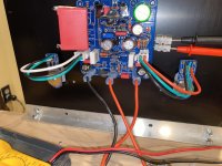
Also does the wiring look correct or have I missed something?
Scott
Well I tried firing one Nirvana board up
And the N channel is not working not sure what I could have missed I have the N channel snubber board diode with line toward bolt end and P channel with diode line toward the connector pins side?
Also does the wiring look correct or have I missed something?
Scott
Attachments
When you say it is not working, what do you mean? No current flows through the source resistor?
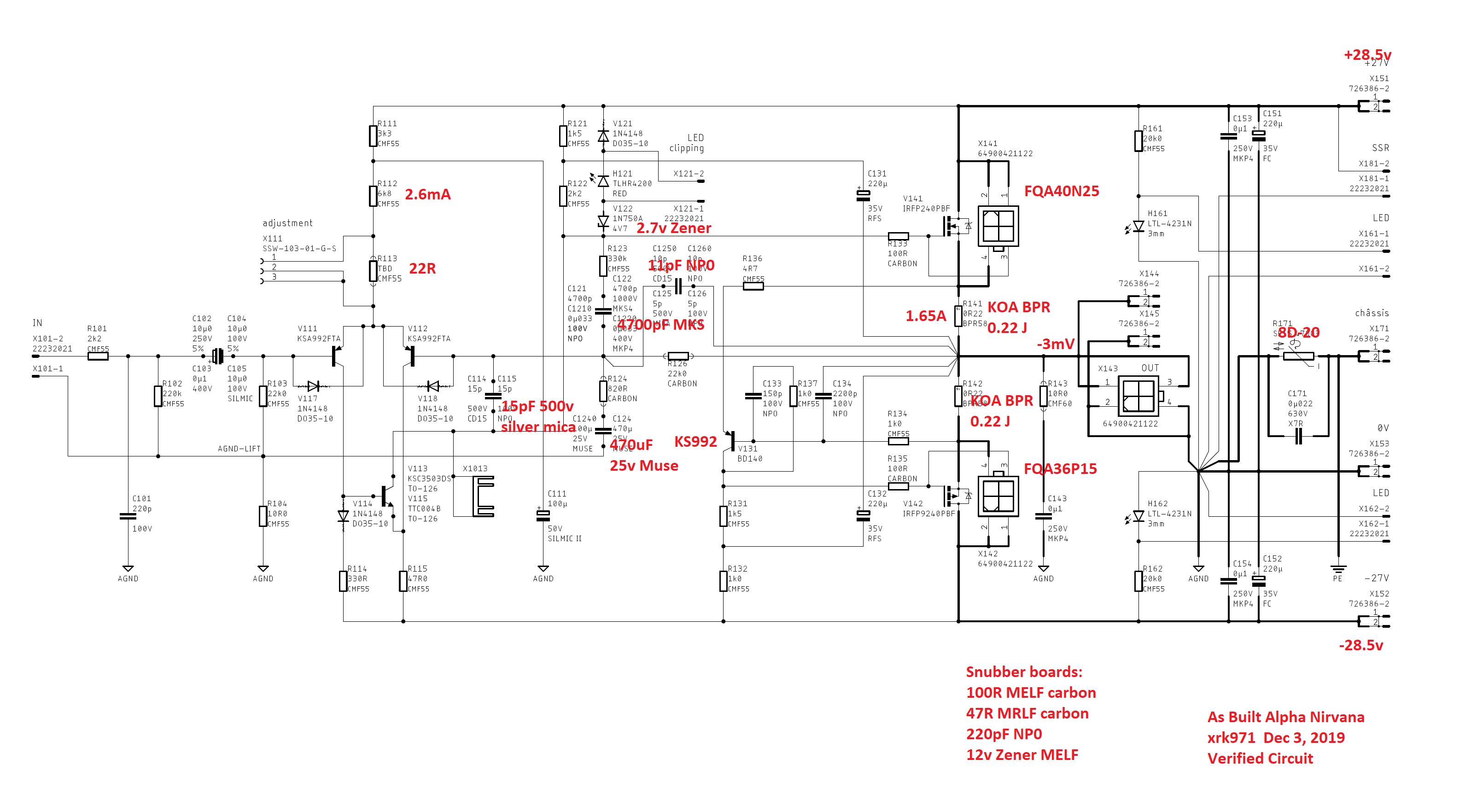
Please measure the voltages at the 3 pins of the MOSFETs (both N and P) with the amp on. Also measure the voltage across the test points for the source resistors. And measure the output node DC voltage. All with respect to 0v or GND. With numbers like this we can start to debug what’s going on.
Usually when there is no current flow, there is a transistor installed incorrectly or the wrong sex. Look at the small BJT controlling the CCS. V131 needs to be a PNP and the pin outs need to be correct.
Other possible reasons are incorrect resistor value (off by 100x etc) in the circuit.
Check V121, H121, V122 diodes. Those control the gate of the N Chan. If they are flipped or incorrect it won’t work. There should be about a 4.5 to 5v drop between the drain voltage and gate voltage if working well. So 27v at D and about 22v to 23v at the G pin.
Last edited:
X,
I will check those out.
Is the source resistor R111?
Also the BJT you are referring to is that
V131 or v115 ?
Scott
I will check those out.
Is the source resistor R111?
Also the BJT you are referring to is that
V131 or v115 ?
Scott
N Channel
25.2v Gate
25.3v Drain
20v source
P Channel
15v Gate
25.4v Drain
19.1v Source
Scott
25.2v Gate
25.3v Drain
20v source
P Channel
15v Gate
25.4v Drain
19.1v Source
Scott
Scott,
Measure base to emitter on V111 AND V112.
The two resistors are R121 and R122.
Actually, from those figures I suspect you have a blown nmos; I think drain and gate are shorted and you should measure that voltage. It should be close to 4.8V, and I think it's far less, maybe only 0.1V. That can only be a broken nmos.
Hugh

Hugh,
I have 0.62 on base to emitters on all 3
Transistors v111 v112 v131 .
I have 0.00 across R121 and R122 .
Measuring from drain to gate was 0.00
Not referenced to ground but just from pin to pin.
Scott
I have 0.62 on base to emitters on all 3
Transistors v111 v112 v131 .
I have 0.00 across R121 and R122 .
Measuring from drain to gate was 0.00
Not referenced to ground but just from pin to pin.
Scott
I would replace both output mosfets, they are common.
You need to have current through those 0.22 ohm resistors, r141 and r142 i believe.
No current, no voltage on those resistors. Just see voltage accross, not against ground.
From voltage drop on those resistors, you easily get current flowing, using ohms law.
You need to have current through those 0.22 ohm resistors, r141 and r142 i believe.
No current, no voltage on those resistors. Just see voltage accross, not against ground.
From voltage drop on those resistors, you easily get current flowing, using ohms law.
I would suspect the N-channel first. But you barely have 4 volts from your gate to source on your P-channel. Your N-channel Gate and Source voltages are the same which is a short.
Also, make sure that after you remove the MOSFETS that you put them on the transistor checker (and post here to show us the results!) and check any new MOSFETS purchased.
After installing the new ones, make 100% sure that the Gate, Drain and Source do not have any connection to chassis ground. They should also not have continuity with each other or else that indicates a failed transistor. I prefer Aluminum Oxide insulators vs Keratherm on Class A amplifiers. Minimizes the chance that the back of the Mosfet (which is the Drain) accidentally shorts to the chassis.
Best,
Anand.
Anand,
Thanks for the input I am changing out the N fet as I type this I have already cut the legs to short to test the one I just removed oh well. I only have an irfp N channel here to try hopefully it will be okay in there.
Scott
Thanks for the input I am changing out the N fet as I type this I have already cut the legs to short to test the one I just removed oh well. I only have an irfp N channel here to try hopefully it will be okay in there.
Scott
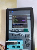
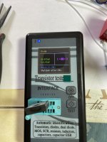
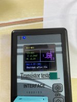
They are both measuring as diodes which is wrong. I am not familiar with this transistor tester model.
Do you have any other MOSFETS you can test, to get an idea of what a normal result looks like?
Thanks,
Anand.
Do you have any other MOSFETS you can test, to get an idea of what a normal result looks like?
Thanks,
Anand.
The pics above show failed transistors. I have a similar tester. Last weekend I was using my tester on Lateral MosFets (2sj162 / 2sk1058) I pulled from a pair of amp boards I am repairing. Five failed out of 8 and with the exception of one of the defective devices they all indicated as the pics above. The odd one out would randomly show a good device or a diode so is not trustworthy.
A normal reading shows the 3 legs of the fuse 😉 and type , whether N or P device.
A normal reading shows the 3 legs of the fuse 😉 and type , whether N or P device.
- Home
- Amplifiers
- Solid State
- Alpha Nirvana 39w 8ohm Class A Amp