Not sure where you get those part numbers? There was a lengthy discussion about V131 around post #1550. In the end it looks like either KSA992 or BD140 can be used here, if I understand correctly. And it is important for me to understand too, since I am about to solder V131 myself any day soon.Could a bc556 be used for V131?
Or is the 2n5401 mandatory?
I'm using BD140. I can see I don't have it in my sim, so posting schematics from that might be misleading.
Ksa992 is almost equivalent to bc556 and you don't need the dissipation of a BD140 in the position of v313Not sure where you get those part numbers? There was a lengthy discussion about V131 around post #1550. In the end it looks like either KSA992 or BD140 can be used here, if I understand correctly. And it is important for me to understand too, since I am about to solder V131 myself any day soon.
Ok, I am out of depth here, but in post #1913 Hugh recommends the BD140 over KSA992 with some technical explanation.Ksa992 is almost equivalent to bc556 and you don't need the dissipation of a BD140 in the position of v313
I’d encourage you to do that Hugh, I think you can tell there is still a lot of interest in Class A, and not everywhere is as warm as Oz ! 😉I know Fab from his work; I will be very interested in his review!!
The single ingredient with my amps is always 'engagement'. I like my music to be involving......
I continue developing the AN in fact. Maybe I will do one for commercial; but a Class A is always very challenging because of the high dissipation and low power; a combination which makes it expensive to build, as you know well.
Hugh
That’s a perfectly acceptable reason not to use it. It might save you from the hassle to have to swap out blown drivers and that’s worth something. My drivers are also $60 but getting harder and harder to find in stock. But the thump protection is nice.
Almost any good audio grade PNP can work here and I think the BD140 has lower Hfe than KSA992 and might be better for stability. Although I have not had a problem. Make sure the pins are correct.Ok, I am out of depth here, but in post #1913 Hugh recommends the BD140 over KSA992 with some technical explanation.
The BD140 has a lower ft than the KSA992 which makes it more desireable.
This relates to a tendency to set up a local oscillation between the BD140 and the pmos, since the pmos is a very high frequency component.
Since the pmos is operated by the BD140, the latter is a master device and if a very fast device it can oscillate, which can destroy the output stage.
This was pointed out to me by Haik, a very smart guy who has unfortunately left the forum. He has done a lot of work with the output stage of the AN, predated it for some years in fact, and I realised he was absolutely right. I have also put in a small cap between base and collector to snub out any oscillation, so you could either the A992 OR the BD140 as XRK has suggested and it will be fine either way.
The A992 (50MHz) is a similar speed device, but the BD140 is just a bit lower (20MHz). These figures are a bit difficult to find, and vary. But given the BD140 can pass 1.5A, I am assuming it is a much larger die, so it will be appreciably slower.
HD
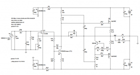
I was just playing with Alpha Nirvana schematic, and decided to try to use JFET op-amp as the input stage.
I actually have never seen class A amp driven by an op-amp, but here it is 🙂
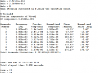
Cheap TL071 op-amp can be used here. This versions seems to be doing fine at 1kHz and 20kHz, and shows
much better sim results than discrete amp.
This is just a proof of concept. Speed, and stability have not been tested, but quick testing in spice so far looks promising.
Hugh, do you think this may work? Besides the fact that some "purists" may be put off by the op-amp...
The VAS transistor seems to be much more stable temperature-wise, than our previous attempt..
Edit: Actually I've seen class A amp driven by op-amp: Calor amp by Bora Jagodic.
I actually have never seen class A amp driven by an op-amp, but here it is 🙂
Cheap TL071 op-amp can be used here. This versions seems to be doing fine at 1kHz and 20kHz, and shows
much better sim results than discrete amp.
This is just a proof of concept. Speed, and stability have not been tested, but quick testing in spice so far looks promising.
Hugh, do you think this may work? Besides the fact that some "purists" may be put off by the op-amp...
The VAS transistor seems to be much more stable temperature-wise, than our previous attempt..
Edit: Actually I've seen class A amp driven by op-amp: Calor amp by Bora Jagodic.
Attachments
Last edited:
Hi Minek,
I used an OPA454 to drive the LuFo (40w) and the SuSyLu (100w). It’s capable of 90Vpp. Sounds quite good and distortion profile is dominated by output stage, which was SE Class A here.
https://www.diyaudio.com/community/threads/lufo-amp-39w-se-class-a-from-28v-rail.372679/

I used an OPA454 to drive the LuFo (40w) and the SuSyLu (100w). It’s capable of 90Vpp. Sounds quite good and distortion profile is dominated by output stage, which was SE Class A here.
https://www.diyaudio.com/community/threads/lufo-amp-39w-se-class-a-from-28v-rail.372679/
Minek,
I certainly looks like it would work well. Very good topology!
It adds a high loop gain in the opamp to the high loop gain from the VAS.
This gives huge levels of nfb, which should deliver very low THD but does it maintain the harmonic profile?
I thank X is right because the sonic overlay is dominated by the output stage, which could be taken out of the fb loop in fact.
HD
Hi,
I hope not to be rude asking how can be implemented the power amp side of this amp to the single ended preamp I've proposed on this thread: https://www.diyaudio.com/community/...channel-dmos-and-not-only.376683/post-6929686
Thank you in advance, and if it not allowed to ask, please delete this post and accept my apologies.
Roberto
X, this profile here is the profile of the Output Stage only, right?Hi Minek,
I used an OPA454 to drive the LuFo (40w) and the SuSyLu (100w). It’s capable of 90Vpp. Sounds quite good and distortion profile is dominated by output stage, which was SE Class A here.
https://www.diyaudio.com/community/threads/lufo-amp-39w-se-class-a-from-28v-rail.372679/
View attachment 1027532
In your Lufo setup, pre-amp and OS have separated feedback loops, and each of these 2 components have it's own "profile".
"Should deliver very low THD but does it maintain the harmonic profile?"Minek,
I certainly looks like it would work well. Very good topology!
It adds a high loop gain in the opamp to the high loop gain from the VAS.
This gives huge levels of nfb, which should deliver very low THD but does it maintain the harmonic profile?
I thank X is right because the sonic overlay is dominated by the output stage, which could be taken out of the fb loop in fact.
HD
Of course not - it doesn't maintain the same profile, as I skipped all your magic profile-shaping RC tricks 🙂
Now we can play with the slope of harmonics.
I bet you can come up with something to shape the profile the way you like it.
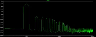
The "bottom" of the new profile is at -170dB, which is exactly where I like it. This level is below measuring capabilities of QA401
analyzer, so in real life we gonna see -120dB when measuring it.
In my sims of AN (at full power), bottom of the "profile" started at -50dB and reached -75dB at 20kHz.
Now it's below -170dB all the way to 100kHz (at all power levels). Peaks of harmonics are all below -80dB, and sloping downwards
from -80dB at 2kHz to -100dB at 10kHz, while Thd stays below 0.002%.
I'm happy with this "profile", but I understand some listeners will prefer higher levels.
The discussion on the subject of perceived advantages of different "profiles" and the content of harmonics is philosophical, not technical
in nature. My position is that real music instruments produce huge amounts of harmonics, on many different frequencies, and as such -
the amount of harmonics added by a semi-decent amp, is like a drop in the ocean. But this is just an opinion.
I think I'm going to build this amp. Of course little bit more work with simulator is needed to make sure it's stable.
Last edited:
What you mean by "zero feedback"? Just by adding bootstrap, you are creating strong feedback loop.The output stage is zero feedback on LuFo.
Even emitter (or source) resistors create feedback loops too.
Regardless of that, the Lufo profile looks as good as it gets....
Last edited:
Hi Minek,
What are the rail voltages on the opamp and is a HV opamp needed? The schematic is still very simple. I look forward to seeing your prototype build.

What are the rail voltages on the opamp and is a HV opamp needed? The schematic is still very simple. I look forward to seeing your prototype build.
Op-amp is powered by 15V rails. It doesn't act a VAS, so it doesn't have to produce rail to rail swing. Q2 will do this.
Maybe this should have it's own thread?
If you have an op-amp that can do it, why not use it as VAS too? Not sure what the output impedance is, but maybe it might even provide better drive (lower impedance) to the mosfet gate? Reduced number of components, -maybe it would increase the OLBW too?
If you have an op-amp that can do it, why not use it as VAS too? Not sure what the output impedance is, but maybe it might even provide better drive (lower impedance) to the mosfet gate? Reduced number of components, -maybe it would increase the OLBW too?
- Home
- Amplifiers
- Solid State
- Alpha Nirvana 39w 8ohm Class A Amp