I just want to report that 470u on the upper bootstrap (C131), and 820u on the lower (C132) gives very little movement of the woofer at startup. Just in case somebody else will build it without output relays, I would recommend these values.
Much too quiet around here. Am I the only one working on the next AN to be born (soon)?
I will be using active cooling with two Sunon fans (with Vapo bearings for what it is worth). They are fed with a 12V 1A wall wart and are running at full speed currently. Question - If I want to slow them down a bit - what value resistor(s) can I try? I have no idea where to begin, except maybe somewhere between 1 ohm or 100k ohm.
I will be using active cooling with two Sunon fans (with Vapo bearings for what it is worth). They are fed with a 12V 1A wall wart and are running at full speed currently. Question - If I want to slow them down a bit - what value resistor(s) can I try? I have no idea where to begin, except maybe somewhere between 1 ohm or 100k ohm.
I'm using my AN as a 'daily driver' now, and I'm happy with it.
Active control of fans would be the best, I think XRK recommended some cheap controllers from ebay that works well.
Active control of fans would be the best, I think XRK recommended some cheap controllers from ebay that works well.
I have been listening to the AN for at least 6 weeks now. I will update the NPXP thread with sonic impressions - soon.
Best,
Anand.
Best,
Anand.
Hi Twocents,Much too quiet around here. Am I the only one working on the next AN to be born (soon)?
I will be using active cooling with two Sunon fans (with Vapo bearings for what it is worth). They are fed with a 12V 1A wall wart and are running at full speed currently. Question - If I want to slow them down a bit - what value resistor(s) can I try? I have no idea where to begin, except maybe somewhere between 1 ohm or 100k ohm.
You can use resistors to slow down fixed speed fans. You need power resistors though like 5W cement filled types. Try 47ohms or 100ohms. You can also string diodes in series and each is 0.6v drop. Be careful of fan stall. Having a high temp sensor tied to the PSU shutdown is a nice feature to have.
I would recommend using Noctua 4-pin PWM fans and $5 Chinese variable speed PWM fan controller. At low speed it is inaudible. It has sensor to kick speed up if temps are too hot.
For example:
https://a.aliexpress.com/_mszxMU0
120mm fan:
Noctua NF-A12x25 PWM, Premium Quiet Fan, 4-Pin (120mm, Brown) https://www.amazon.com/dp/B07C5VG64V/ref=cm_sw_r_cp_api_i_FZGCFX4SR3ZX89EB7F49?_encoding=UTF8&psc=1
They come in all sizes, larger ones are quieter. There is also a “speed reducer” which is probably some diodes in series to give voltage drop.
Last edited:
Thank you X - I will experiment this weekend with some resistors, now that I have an idea what to aim for. Yes, I know about Noctua fans and fan controllers (from discussions in the ABBB thread), but I am a cheap and frugal amp builder. First want to try with the Sunon fans. Got them cheap locally.
in my thread 'viral projects' I recommend cheap but good fans from parts express, totally quiet when run on half volts
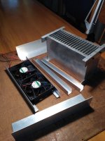
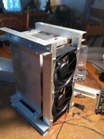
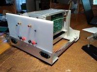
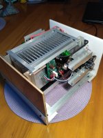
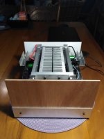
Another AN up and running. It’s been running for a few days now with no signs of self-destruction, which is a great achievement for an amateur like me. Not the greatest looking build, and I am hesitant to post pictures here – but boy oh boy, I am sooo happy with the sound. The enclosure is put together from scrap aluminum and repurposed heatsinks from my ACA amp. The footprint is small, and I could hardly fit the Cap Multipliers inside. Active cooling using two SUNON 92mm fans powered from a separate wall wart. Main PSU is 4 x cheap smps (24V 6A) supplies with 4 x DC DC boosters in series to give dual +/- rails feeding into Gtose/M Johnson Cap Multipliers, one for each channel. All this delivers exactly +/-27V rails to the AN boards. Despite the two fans the amp is running quite hot to the touch. The heatsinks are maybe bit too small, but it is not overheating.
Built using the values and mostly the same components as X's “Proto Schematic As Built Dec 3 2019”, except for V131 and C125/126. For V131 I used BD140, based on further discussions and recommendations from Hugh. For C125/126 (11pF NPO) I used two 5.6pF COG SMD caps stacked (parallel) to give close to 11pF. Between the 4 suppliers (two local and two in the USA) I used, I could not get 11pF NPO or Silver Mica at the time. Currently with Elna Silmic II input caps.
Absolutely no tweaking or adjustments were necessary. Voltages across R111 measures 8.53V and 8.50V respectfully, which sets the LTP bias to 2.57mA. DC Offset measures -5mV and -4mV respectfully. With inputs shorted the DC offset drops to -3mV. I am an extatically happy AN owner!
How does it sound? All I can say is - it just sounds so so musical. Great detail. Great soundstage and imaging. Great control over mid and low bass. I love this amp’s sound.
Thank you very much X, Hugh, and all the others that contributed here.
Attachments


twocents,
Congratulations on completing the build - You've been quite innovative with your approach with power, cooling, and chassis and have pulled it off nicely. 🙂
A great design by Hugh, and very nice of him to share it with community.
Congratulations on completing the build - You've been quite innovative with your approach with power, cooling, and chassis and have pulled it off nicely. 🙂
A great design by Hugh, and very nice of him to share it with community.
Thanks zman. I am a frugal builder, but the SQ and satisfaction I achieved since starting this diy hobby 5 years ago is priceless for me. I could never have done it without this forum and helpful members. I thank you all for sharing your knowledge and experiences, and a special thanks to X. He has been the main culprit and inspiration for most of my builds to date.
Wow two cents another AN is born - congratulations for a long gestation!
My design brief was 'tube grace and SS muscle' so let's hope you love it as well in six months!
Hugh
My design brief was 'tube grace and SS muscle' so let's hope you love it as well in six months!
Hugh
Thanks Hugh. Yes, 'tube grace and SS muscle' sums up exactly what I am hearing. One of the tracks I use for testing is Adele’s Hello. But playing it real loud. From around 1:07 this song becomes a real challenge for amp and (especially my full range) speakers to remain un-congested – to maintain her vocal clarity and rest of the music un-warped. Sorry, I’m not great with describing what I am hearing. Unlike my chip amp the AN remains calm and in control and the speakers just remains crystal clear in all frequency bands. It’s just so easy to listen to, even with load music. Thank you for a great diy amp!
Congratulations Twocents!
I really like your innovative build and use of existing components and materials. I think amp chassis made with aluminum L extrusions are super. Two L extrusions and a plywood plank provide a front and rear panel. Add the heatsinks and fans and you are set. Since you are using SMPS and cap multipliers, I would venture to say your amp is absolutely hum/noise free with ears pressed to the cone when no music is playing. In many ways, a hand made chassis from commonly available parts is much more rewarding than a prebuilt chassis that anyone can buy. I’m glad you stuck with it and now enjoying the fruit of your efforts.

I really like your innovative build and use of existing components and materials. I think amp chassis made with aluminum L extrusions are super. Two L extrusions and a plywood plank provide a front and rear panel. Add the heatsinks and fans and you are set. Since you are using SMPS and cap multipliers, I would venture to say your amp is absolutely hum/noise free with ears pressed to the cone when no music is playing. In many ways, a hand made chassis from commonly available parts is much more rewarding than a prebuilt chassis that anyone can buy. I’m glad you stuck with it and now enjoying the fruit of your efforts.
Super cool work Twocents!! Congrats on getting your AN successfully fired up and sounding great. Your amp module is very neat and compact, just be sure you don’t forget to turn the fans on 😳
ENJOY!!!
ENJOY!!!
How did you connect the upper bootstrap cap? To the output or the source of the upper FET? We discussed it a bit earlier in the thread. I suggest you try both and see what you prefer (If you feel like experimenting). I found I prefer it from the source, but this may vary. I think I'm the only one who tried it so far? I would be interested in other peoples opinions in case somebody else tried it.Thanks Hugh. Yes, 'tube grace and SS muscle' sums up exactly what I am hearing. One of the tracks I use for testing is Adele’s Hello. But playing it real loud. From around 1:07 this song becomes a real challenge for amp and (especially my full range) speakers to remain un-congested – to maintain her vocal clarity and rest of the music un-warped. Sorry, I’m not great with describing what I am hearing. Unlike my chip amp the AN remains calm and in control and the speakers just remains crystal clear in all frequency bands. It’s just so easy to listen to, even with load music. Thank you for a great diy amp!
A question for Hugh or X...
Imagine if one had a plethora of N channel JFETS, i.e. SemiSouth SJEP120R100's.
Can one replace M1 (in Hugh's original schematics on page 1 of this thread) or V141 (in X's schematics on page 1 of this thread - the one with red correction marks)? M1 or V141 is the main N channel MOSFET amplification device that has voltage control of both the positive and negative half cycles (and only current control of the positive half cycle).
I was curious given that it has a very prominent sonic impact and responsibility in this circuit.
The question really boils down to whether the SJEP120R100's have lower intrinsic distortion than the FQA40N25 or IRFP240 and how that translates from a subjective standpoint. I am willing to be the guinea pig and experiment of course but I need a Hugh blessing first (!), given the costs of the SS SJEP120R100 and my relative unfamiliarity with Hugh's CCS (vs Pass' Aleph CCS).
Thanks,
Anand.
Interesting question, Anand.
I think a SJEP would be OK. It certainly won't cause any issues because these devices are rated to 17A and 1200V.
I am not certain about gate current, but the curves reveal it should operate with about Vgs of 1.5V, compared to the hexfet of 4.3V.
This should give good results. My only concern is whether the gate will require current drive; I don't believe so at these low voltages, but these are very stable, strong and thermally robust devices. Transconductance appears to be about 15S; the IRF240 is about 6.9 so you could expect less distortion.
When you install, measure the Vgs (gate to source) and then measure any voltage across the gate stopper. I believe there will be no gate current, like a hexfet, so it should be fine. You could only replace the upper mosfet, of course; the lower, CCS hexfet should be retained.
Hugh
Hugh,
I will do so. I imagine the measured Vgs will be 1.5V or thereabouts (Pass mentions 1.2V in his F6 document)and hopefully there will be no voltage across the gate stopper which would mean there would be no gate current. If there is a measured voltage across the gate stopper resistor, I’ll let you know here. Per Pass the use of the SS SJEP120R100 could provide 10-20 dB less distortion.
Best,
Anand.
Last edited:
- Home
- Amplifiers
- Solid State
- Alpha Nirvana 39w 8ohm Class A Amp