your making me jealous! no class A for you! 😀😀😀
The timer would operate the relay to drop the thermistors out. They would be on the 12vdc control circuit.I don't think those will work. it says a max continuous load of 1A.
From your rails biasing to 50W will already take you up to a 1A draw!
In my case I used a very simple RC timing circuit to control two relays to switch the thermistors out after about 18 secs.
Its crude, but it works.
However I would use something like what BigE designed. Its safer and disconnects the relays as soon as power is switched out.
http://www.diyaudio.com/forums/powe...it-design-other-psu-issues-4.html#post4029746 (post 39)
BTW. Just saw your secondary boards. What size resistors are you using for source resistors?
Sorry, I can follow schematics and directions, but still learning the language so to speak. What position is the "source" resistors? R15 and R16 are 47r5 and R21-24 are 1ohm, as per schematic.
I was asked to come to Hawaii for a special project about 4 years ago. The project is long over, but I haven't found a reason to leave!your making me jealous! no class A for you! 😀😀😀
PICS in the pics thread! or it aint true! 😀😀😀
Cell phone shots ok?
The timer would operate the relay to drop the thermistors out. They would be on the 12vdc control circuit.
Sorry, I can follow schematics and directions, but still learning the language so to speak. What position is the "source" resistors? R15 and R16 are 47r5 and R21-24 are 1ohm, as per schematic.
re- the SS timer - Yep true sorry wasn't thinking correctly.
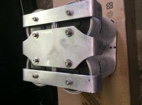
The source resistors are the 1 ohm ones. what power rating are they? They seem a little small....
Should I use 2 pairs of JFETS? (Q1-2, Q1.1-2.1) I bought 2 sets of quads.
The NP article suggests that one pair is enough for up to 4 pairs of output devices.
That being said, has anyone actually utilized the second pair?
Thanks for the continued support!re- the SS timer - Yep true sorry wasn't thinking correctly.
The source resistors are the 1 ohm ones. what power rating are they? They seem a little small....
They are 5watt Mills
Thanks BigE! I guess I have spare set.The NP article suggests that one pair is enough for up to 4 pairs of output devices.
That being said, has anyone actually utilized the second pair?
Thanks for the continued support!
They are 5watt Mills
Ah ok, they are rated plenty high enough. They just looked small from the pic...
Thanks for the link! I'll look it up when I get home tonight.
Andrew can you explain "Low Loop Area philosophy"? No hits on Google.Plates, like PCB traces, defeat the Low Loop Area philosophy.
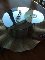
The first one of the pair of Toroidy Transformers arrived yesterday. I guess between Poland and Hawaii they got seperated😥
I knew the actual size, even made a template to use while I was building the chassis so I knew it would fit, but sure looks bigger in person. 28 1/2 lbs.
The case is a work of art, a shame to hide it!

I knew the actual size, even made a template to use while I was building the chassis so I knew it would fit, but sure looks bigger in person. 28 1/2 lbs.
The case is a work of art, a shame to hide it!

The first one of the pair of Toroidy Transformers arrived yesterday. I guess between Poland and Hawaii they got seperated😥
I knew the actual size, even made a template to use while I was building the chassis so I knew it would fit, but sure looks bigger in person. 28 1/2 lbs.
The case is a work of art, a shame to hide it!
View attachment 445306
Awesome ...
A loop can be a receiving aerial or a transmitting aerial or both.
Pass a varying current around a loop and the aerial transmits radiation.
Place a loop inside a varying field and the aerial receives radiation.
Eliminate the loop and you eliminate the radiation, a bit too simple but it is the part I need for this explanation.
Make a loop and you are in effect making a circuit that will emit and receive radiation.
Your three plates are circuits with Loops.
They pass large varying currents around the Loops.
They will emit radiation.
Every other loop inside your amplifier will pick up some of that radiation.
Low Loop Area is a simple topology to eliminate radiation interference.
- Status
- Not open for further replies.
- Home
- Amplifiers
- Pass Labs
- Aloha F5 v3 Monoblock build

