Thanks for commenting on my project! I just ordered the power switch driver boards from amb. I should receive the push button off/on switches tomorrow from Mouser and had just started looking for a control circuit.
Have you used the SS relay? Curious about performance.
I use recommended relay but smaller one for up to 30A! Also - dont forget to order transformer board from AMB! If you cant find recommended small trannie i think i have one or two .... Everything working flawlessly ... in F5 and DCB1
One thing that you need to remember is the fact that the amp is a Class A amplifier.
This means it draws current at all times unlike class A/B.
This will mean that the thermistors will ALWAYS be hot and should be sized for that fact. Those thermistors take at least 2-3 min to cool!
Looks like Ametherm went the really safe route and suggest a thermistor per cap! wow! not sure if that will be ideal for an amp.
According to some here, thermistors should always be taken out of circuit after the initial charging. In my case they are switched out with relays.
I used the Ametherm MS32-10015 one per rail in the slow charge and switched out after about 20 seconds. In the soft start circuit, I use the same one, but you can get away with something a lot smaller since it only starts the transformer.
Yes I had to make my own timing circuit for the slow charge. There didnt seem to be many simple designs for sale so I had to DIY it 😀.
Regarding SS relays, I wonder if anyone ever measured them through a scope to see if they feedback any noise ?
Thanks as always for commenting!
The reply from Ametherm mentions "steady state" I would assume means "constant draw"? I didn't mention how many individual capacitors in each monoblock, so I don't think "per cap" means "per capacitor"? I'm such a noob I haven't replied yet to ask for clarification. Would it make sense to mean per monoblock?
Well if you send me link with capacitor datasheet i can make design for individual an all capacitors, for easy and clean connection for caps thermistors and resistors perhaps ? You can make them cheapo on oshpark
Ametherm's answer (post98) is a slow charge resistance using 2off ms35, one for each capacitor bank in the secondary circuit and a relay bypass across each MS35.
You still need a soft start to get the transformer started without blowing the Mains fuse.
You still need a soft start to get the transformer started without blowing the Mains fuse.
Last edited:
That amb circuit is only good for a turn on switch. Not a soft start.
I used this :
Connexelectronic
I substituted the thermistor they had in there for the ametherm one.
Bonus is that it also has a low voltage switch control as well! so no need for a separate board. This will take care of your soft start and switch.
Of course as AndrewT says, you still need a slow charge.
I used this :
Connexelectronic
An externally hosted image should be here but it was not working when we last tested it.
I substituted the thermistor they had in there for the ametherm one.
Bonus is that it also has a low voltage switch control as well! so no need for a separate board. This will take care of your soft start and switch.
Of course as AndrewT says, you still need a slow charge.
Yeah but that won't help with soft start or slow charging his amp.
I wonder if it will handle the amp? I bet the 2 1500VA trafos may be choked by that power centre.
Thanks all for your comments and suggestions!
Ametherm also sent this sketch;
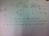
Should have posted earlier!
Since I'm using a push button switch, need contactor to remove thermistors, need temperature protection, and installing a small DC fan w/control, it looks like I will need to put a whole control circuit together. With the fan I will need a larger transformer than the one on the turn on board.
A little planning ahead!
Ametherm also sent this sketch;

Should have posted earlier!
Since I'm using a push button switch, need contactor to remove thermistors, need temperature protection, and installing a small DC fan w/control, it looks like I will need to put a whole control circuit together. With the fan I will need a larger transformer than the one on the turn on board.
A little planning ahead!
Coast,
I can't read all your notes.
At least two are wrong.
You said "As S is thrown (closed) NTC blocks Inrush current".
No, it does not.
The NTC is an added resistance in the primary circuit. The total primary circuit resistance limits the start up current. It is NOT "blocked".
Then "Once the coil is activated the NTC is out of circuit.".
No. Once the contacts close the NTC is effectively out of circuit.
After coil current starting to flow, there is a time delay until the contacts close and stay closed.
Last edited:
Coast,
I can't read all your notes.
At least two are wrong.
You said "As S is thrown (closed) NTC blocks Inrush current".
No, it does not.
The NTC is an added resistance in the primary circuit. The total primary circuit resistance limits the start up current. It is NOT "blocked".
Then "Once the coil is activated the NTC is out of circuit.".
No. Once the contacts close the NTC is effectively out of circuit.
After coil current starting to flow, there is a time delay until the contacts close and stay closed.
Andrew thanks for the reply. The sketch and notes are from Ametherm, FYI.
I'm assuming that you are further defining the statements, i.e. "Blocked" vs "limits" and "out" vs "effectively out", as to the actual schematic your good with it?
Andrew thanks for the reply. The sketch and notes are from Ametherm, FYI.
I'm assuming that you are further defining the statements, i.e. "Blocked" vs "limits" and "out" vs "effectively out", as to the actual schematic your good with it?
I will comment on the circuit you posted as is. Please forgive me if these points are assumed or described elsewhere.
1) For safety reasons, mains AC voltage should first come to a fuse. A slow blow will be good.
2) The way it is drawn, when the relay closes not only is the NTC bypassed, but also the coils, which will drop out, and the relays will open again. You will get a nice chattering sound.
3) I am not sure what the bridge is supposed to do, but one thing it does is effectively short the negative half of the sine wave to ground...Not good.
4) No current will flow to the other side. Please explain what you are trying to do so we can offer a suggestion.
I had asked Ametherm for help choosing the correct size and locations for both soft start and slow charge NTC's for my amp build in progress. Besides their answer they sent the sketch.I will comment on the circuit you posted as is. Please forgive me if these points are assumed or described elsewhere.
1) For safety reasons, mains AC voltage should first come to a fuse. A slow blow will be good.
2) The way it is drawn, when the relay closes not only is the NTC bypassed, but also the coils, which will drop out, and the relays will open again. You will get a nice chattering sound.
3) I am not sure what the bridge is supposed to do, but one thing it does is effectively short the negative half of the sine wave to ground...Not good.
4) No current will flow to the other side. Please explain what you are trying to do so we can offer a suggestion.
Chassis construction continues. My 80mm fans arrived yesterday so I cut those in.
I wanted rounded corners on my heatsinks, so I first ran them all through the table saw and cut away most of the corner. Then today I used a 1/2" carbide round over bit to finish the shape. Finish sanding still needs to be done.
The large cap Rifa's have a bolt on the bottom that protrudes about 13mm. I didn't really want to have exposed nuts on the bottom of the chassis so I built a little platform for them to sit on. Probably keep them a little cooler also.
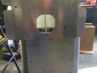

Don't forget to use these to isolate the stud of your caps from the chassis.
PYB7026 - KEMET - NYLON CAP NUT, M12 | Farnell UK
PYB7026 - KEMET - NYLON CAP NUT, M12 | Farnell UK
I didn't know that they needed to be isolated. Thanks for the info.Don't forget to use these to isolate the stud of your caps from the chassis.
PYB7026 - KEMET - NYLON CAP NUT, M12 | Farnell UK
Received an email from Toroidy, their epoxy machine is under repair, so my transformers haven't shipped yet. So against my own advice I went ahead and started installing the boards, drilling all the penetrations.
I'm mounting the N and P channel boards to the 2" piece of aluminum that secures the middle of the upper and lower sinks. I countersunk the screws under the boards and used 3 washers to space the 2" strip away from the sinks for an air slot. The goal is that since this slot on each side is the only opening in the chassis that the air from the fan will inject cooler air between the sinks and at the same time cool the interior of the chassis.
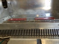
I am using the Schuter push button off/on switches. Mounting location will seem odd now, but not after complete. FYI, red led.

So I made a paper transformer to confirm layout. Everything in the pictures are mounted to the chassis. All hardware is either brass or stainless steel. I forgot to bring the balanced inputs to the shop, so those are left to go, also I have left an area on the floor in front of the fan for a separate 12vdc power supply for control. Due to space I split the DIY power supply boards and will stack to make more room. I will have as part of the control circuit high temp cut off. I also plan to set a fan on temp switch to allow the sinks to heat up and stabilize quicker before the fans start.
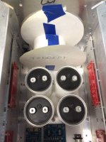
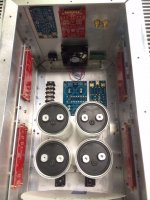
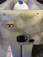
Here is a rough layout of the Mosfet's and mur3020's, Mosfet's on bottom. The sinks are 5" tall so planning on tapping for the mounting screw 2" up from the bottoms and center side to side of each sink.
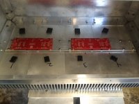
So what do I have right and wrong so far?
I'm mounting the N and P channel boards to the 2" piece of aluminum that secures the middle of the upper and lower sinks. I countersunk the screws under the boards and used 3 washers to space the 2" strip away from the sinks for an air slot. The goal is that since this slot on each side is the only opening in the chassis that the air from the fan will inject cooler air between the sinks and at the same time cool the interior of the chassis.

I am using the Schuter push button off/on switches. Mounting location will seem odd now, but not after complete. FYI, red led.

So I made a paper transformer to confirm layout. Everything in the pictures are mounted to the chassis. All hardware is either brass or stainless steel. I forgot to bring the balanced inputs to the shop, so those are left to go, also I have left an area on the floor in front of the fan for a separate 12vdc power supply for control. Due to space I split the DIY power supply boards and will stack to make more room. I will have as part of the control circuit high temp cut off. I also plan to set a fan on temp switch to allow the sinks to heat up and stabilize quicker before the fans start.


Here is a rough layout of the Mosfet's and mur3020's, Mosfet's on bottom. The sinks are 5" tall so planning on tapping for the mounting screw 2" up from the bottoms and center side to side of each sink.

So what do I have right and wrong so far?
- Status
- Not open for further replies.
- Home
- Amplifiers
- Pass Labs
- Aloha F5 v3 Monoblock build


