This might work well too. Nice one I think:
Did some simulations
The schematic in black pic has more distortion.
Did now all types, alexander, bootstrap, only opamps.
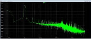
pic 1 = alexander current feedback like.
pic 2 = Old X specified design (opamps)
pic 3 = kees bootstrap (I did).
pic 4 = X his bootstrap design.
not much different in hd so far, all output is full power..
Attachments

Maybe we could use lateral mosfet in compound too
what do you use as driver ?
if you want made all vertical fet we could made this :
https://circlotron.audio/sites/default/files/2020-06/nofeedback.png
Using lateral in compound is possible, I use this configuration so I do not loss a lot of signal, compound is local feedbacked.
Possible when do this with laterals it can drift also, the wrong direction and loss of idle current, using a IRF 610 with a lateral can be used.
But laterals is a disappairing mosfet, or really expensive.
I think a autobias here does wonders. Compound is difficult to get stable with a bias servo, it can be done but is much more effort to get it right.
Using vertical mosfets the way I see on the pic without feedback, I do not think that will sound right, laterals are here much better, more even
harmonics, verticals does the nasty uneven ones very strong.
regards
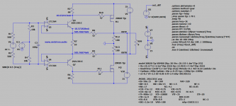
The first design is the one following paper by S Dogran, and the one in black is design by W Kirkwood. None are of my own design. I like the one you did too.
But 5th order is high and that can cause a bit of fatigue. Whereas the Kirkwood one is monotonically decreasing higher order distortion and less fatiguing.

But 5th order is high and that can cause a bit of fatigue. Whereas the Kirkwood one is monotonically decreasing higher order distortion and less fatiguing.
Hi X
The version with only opamps does quite good in output power thanks to the compound stagess, now we do not loose 2 x the gate source treshold voltage anymore but bias is more difficult, so autobias is a good idea.
I go make a board for one, using opa1632 because have no other one like the 604, but with the bootstrap it can have higher voltage.
Was the version with the opamps alone not from you? the one you did mention long ago?.
Oke not that important, the alexander and the bootstrap are also not from me, but is there already for years, so why not using it.
Do now X the simulations are on high power, almost max, that is already nasty to listen to. But I have more testings.
regards
Last edited:
I see you have some knowledge about ltspice? I have a lot of trouble simulating with the opa604 opamp or others in the ltspice directory, get a lot of defcon and it does not simulate, it hangs on defcon.
About your idea, a jfet is a little weak to drive a powermosfet because of gate capacitances and voltage.
regards
About your idea, a jfet is a little weak to drive a powermosfet because of gate capacitances and voltage.
regards
Attachments
Last edited:
Ux86,
I like CFP’s - looks nice. I have heard that having the Source facing the load provides a more definite voltage drive, whereas having the Drain facing the load, the voltage at the load is indeterminate. Would using 2SC3503 drivers for P-ch MOSFETs work better? I think it might lower the output impedance.
I like CFP’s - looks nice. I have heard that having the Source facing the load provides a more definite voltage drive, whereas having the Drain facing the load, the voltage at the load is indeterminate. Would using 2SC3503 drivers for P-ch MOSFETs work better? I think it might lower the output impedance.
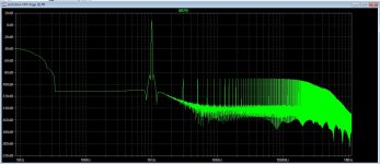
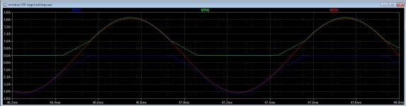
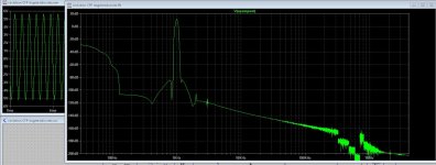
X The distortion is much lower when I let ltspice run later, so the autobias can ramp up first.
Autobias pic you see it does track nicely.
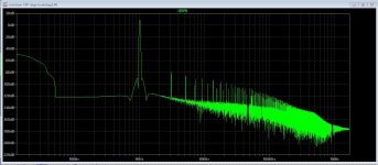
pic 3 is the cfp version also better when ltspice does sim later for ramp up first. CFP has more distortion but looks stil nice.
regards
Autobias pic you see it does track nicely.
pic 3 is the cfp version also better when ltspice does sim later for ramp up first. CFP has more distortion but looks stil nice.
regards
Attachments

Last edited:
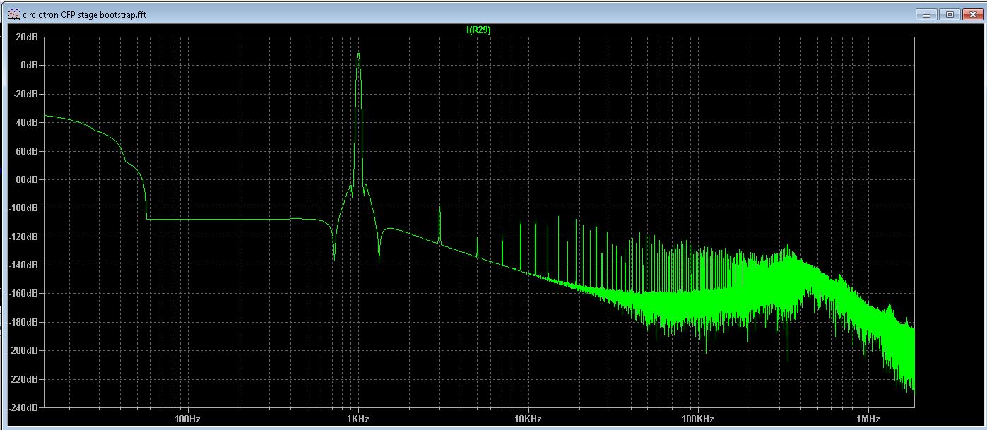
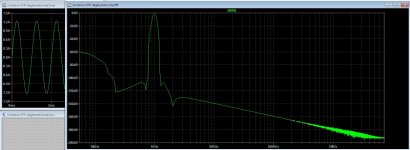
Some corrections in the bootstrap version.
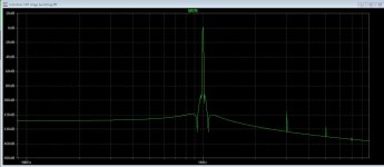
A lot depents of opamp and model, I have now include a follower for low output impedance, see the distortion with 2 amps out, quite low right? the follower is in class A.
regards
A lot depents of opamp and model, I have now include a follower for low output impedance, see the distortion with 2 amps out, quite low right? the follower is in class A.
regards
Attachments
That looks really low THD but I would rather give some of that up for dominant H2. Maybe make R16/17 a little asymmetric.
Maybe local feedback setup?
Well I did try, more distortion but still the second harmonic is not present.
You do now why i presume? the circlotron is a balanced amplifier these do cancel out even
harmonics, that is maybe a problem but only after build we can see that.
Only single ended amps has this prefered harmonic content, that is why these are so loved.
I can change some things like use a single ended driver but I am afraid that also then the
output stage will still cancel it out, a little more unbalance as you did mention I go try later.
regards
Last edited:
Hi kees
I see that you reuse what I proposed in 2019
OPA604 Circlotron | Circlotron Audio
http://circlotron.audio/data/simulation/img/opa_B.png
how do you bias the output stage? with the voltage source on opamp input ?
Ahh now I read good, do not always do this, I see the proposed amp was not from X but from Ultimate, sorry guys that I did mixed you up.
In the meantime you see that I do use the opamp inputs for the bias (automatic).
I have now extended this idea and it get some more complicated.
regards
X
I did make some unballance in the amp but the autobias does not like it, giving uneven idle current because this resistor is made smaller.
but hd is some more friendly but still a formidable -150dB, we need to make the unbalance on a other place for not to provoke the autobias.
regards
I did make some unballance in the amp but the autobias does not like it, giving uneven idle current because this resistor is made smaller.
but hd is some more friendly but still a formidable -150dB, we need to make the unbalance on a other place for not to provoke the autobias.
regards
Attachments
Last edited:
Hi Kees,
Let me know when you think the schematic is done - I'll ask JPS64 if he can make us a nice layout. I think this result is quite phenomenal if we can achieve it in practice! -150dB is below what an AP can measure I think. You need specialized equipment like notch filters and high gain amplifiers to boost the distortion to measurable levels.

Is it this schematic but with some asymmetry added to the resistors as I suggested?
Let me know when you think the schematic is done - I'll ask JPS64 if he can make us a nice layout. I think this result is quite phenomenal if we can achieve it in practice! -150dB is below what an AP can measure I think. You need specialized equipment like notch filters and high gain amplifiers to boost the distortion to measurable levels.
Is it this schematic but with some asymmetry added to the resistors as I suggested?
Last edited:
Hi X
This schematic I did have set the amp asymetric but then I get a lower Idle current on the side where the resistor is smaller, so this does not work fine.
I think because the deep distortion level of -150dB this change will not be audible at all, even with uneven distortion it is not audible, with low 1 amp power I think distortion is even not present..
Before make a pcb, we need to build it first, I can also make the pcb but if you want to let it do by SPS64 this is fine for me.
Busy now with a discrete opamp, look what it does and such.
Do now, in practice it will be different afcourse. The version with the two opamps from ultimate does also low, and is quite simple, because this opa604 can withstand 24 volts x 2 you get still 80 watts.
Last edited:
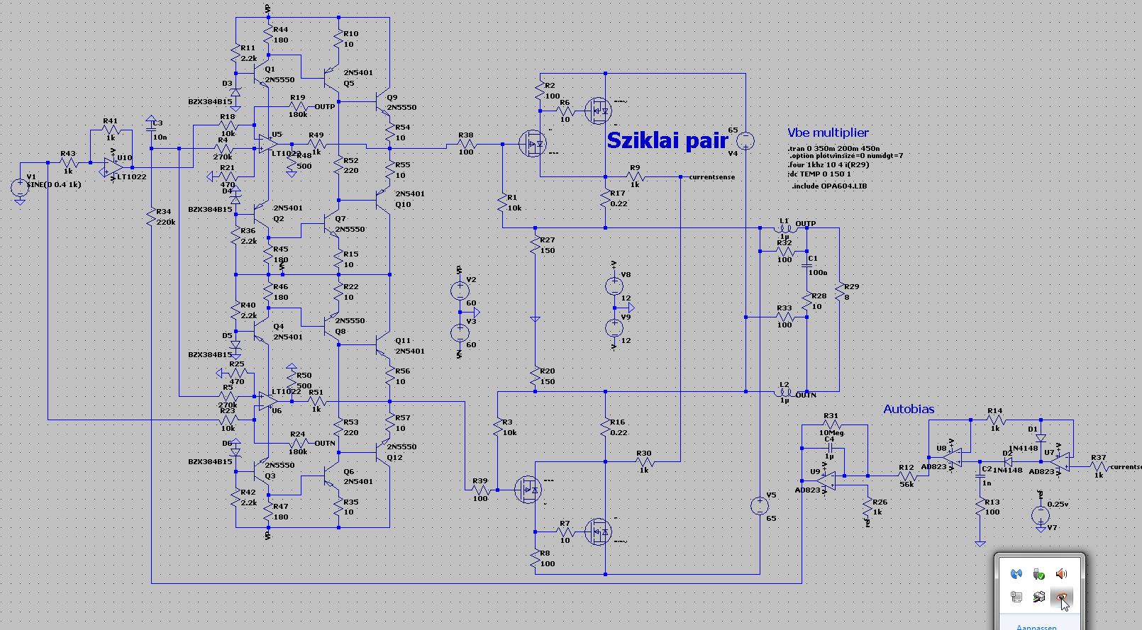
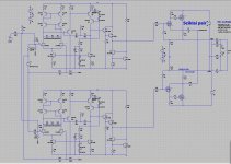
Th discrete version of a opamp, just a example of a modern good sopunding one and have fill in the vaues of resistor etc.
Can on hogher voltages and the respons, like with some more even harmonics is done be playing with the idle current through the transistors.
I have much open loop with the wilson mirrors and cascode.
it can supply easely the output signal for the mosfet stage for high power.
Is somebody see some strange values of resistors or so, just let me now, because recalculating that is not so mine thing.
regards
Attachments
Discrete OpAmp
hi,
The input-impedances on the gates of J1 and J2 should roughly equal.
Be aware that the high feedback resistor value would contribute to the output noise.
Analog Circuit Design · Samuel Groner · Resources · Discrete OpAmps
hi,
The input-impedances on the gates of J1 and J2 should roughly equal.
Be aware that the high feedback resistor value would contribute to the output noise.
Analog Circuit Design · Samuel Groner · Resources · Discrete OpAmps
Last edited:
Een goede avond Piersma, welkom.
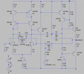
Oke yes you are right, I see 10k and 1k originally here are bjt no jfet but get strange things then, I think jfet is more easy for this function.
The big 330k resistor is just for test, later on it get into the circlotron and retest, now it is to adjust things, who is not that easy with these cascodes.
I just play now some with this stuff, unfortaney jfets are not made anymore I do like a allfet more special with jfets like borbelo did.
regards
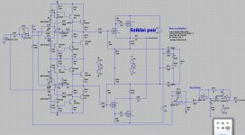
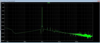
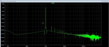
Here is a discrete version, with a discrete opamp, this one is free to use and has single ended current source loaded outputs, the harmonic content is friendly now. the previous discrete version is deleted.
On the output of the circlotron is the harmonic content canceled out, AI do not now how it sounds with such a low distortion, building one will tell.
now the diamond input current feedback as last, if someone will schematic to simulate thereselfs let me now.
second pic is the output opamp before mosfet powerstage, see it has nice harmonic content.
regards
Attachments
Last edited:
- Home
- Amplifiers
- Solid State
- allFET circlotron