More measurements
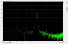
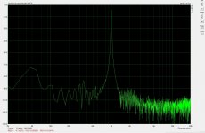
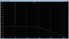
I get very low distortion when not load the amp, but with load it go up to 0.35 % (from 0.0*) I gess the lab supply of 3 amp max do cause that, it is not made for that. Last picture you can see the loaded amp.
I have low feedback now also, the open loop is not that big.
Sound sample tomorrow. a drum piece, amp is bloody fast..
regards
Attachments

did put two coils in for zobel.
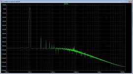
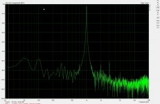
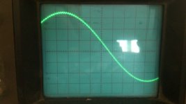
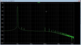
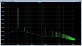
this is result in real live, distortion is quite higher then without a load, possible the lab supply is the reason, to high output impedance or so, or through the feedback path there get things messed up, it is mucho even harmonic, and strange it is only the second and thirth HD others are far away..
Amp do sound quite a lot better now as before, the extra driver do well driving the big irfp gate capacitance in class a.
picture 1 without load, second with it.
regards
Attachments
Kees
maybe I`m wrong but I think that your lab supply unit introduce some negative influence on amp output charateristic .
maybe I`m wrong but I think that your lab supply unit introduce some negative influence on amp output charateristic .
I ageee. Lab supplies are meant to be variable and noise is secondary. I am a big believer in cap multipliers for class A.
So 24v rails from 33mF//0.125R//33mF then output to Zuma's cap multiplier gets 20v DC rails with ripple down to 0mV at 1.5amp load. It is dead quiet and allows true amp noise or lack of or to be heard. One can size trafo 5v higher to keep same 25v nominal rails after the multiplier.
So 24v rails from 33mF//0.125R//33mF then output to Zuma's cap multiplier gets 20v DC rails with ripple down to 0mV at 1.5amp load. It is dead quiet and allows true amp noise or lack of or to be heard. One can size trafo 5v higher to keep same 25v nominal rails after the multiplier.
Kees
maybe I`m wrong but I think that your lab supply unit introduce some negative influence on amp output charateristic .
That is what I also think.
There are also some burtst on the supply, and coming from the lab supply, but fior protection while experiment such supply is very handy.
I go try tomorrow a cap version, 10.000uF, res 10.000uf.
the amps do sound fine, but I think the laterals are better sounding, try that
also in time.
Maybe the lab supply has a to high impedance to the amp itselfs.
regards
So you are still running real live circuits on that old board? I thought your mods would have been too extensive to get working on the old circuit layout. Do you have a photo of the board as it is currently configured?
So you are still running real live circuits on that old board? I thought your mods would have been too extensive to get working on the old circuit layout. Do you have a photo of the board as it is currently configured?
Yes I did, I am handy you now, but it is not suitable for do it yourself, I do make a new board, did think about laterals also, even for the drivers (irf610) change for a lateral, for me the sound of them is much better, but first I go make the supply and disconnect the lab supply and see what happens.
regards
Attachments

For as I did read about good sounding amplifiers source or cathode followers are not a way to help with that because of the 100% feedback and so low impedance, but with class a drivers we have also quite low impedance and no feedback.
I have made it test amp with this, the output circlotron has only drain followers and a licht current feedback so it amplifies a little, like a compound amp, so we have a compount circlotron here, however what it does with idle current runout I do not now, because it amplify also the thermal runaway, we need here laterals to prevent.
this amp has only local feedback paths and only current, so for later, I go try this some day.
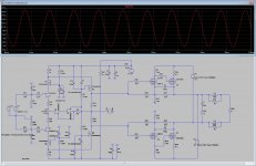
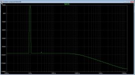
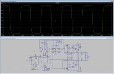
50 Khz square is oke above that it get worse but it is already very fast on 50 khz, 20 Khz square is already mucho enough, above that things get only unstable.
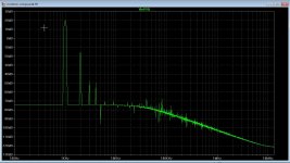
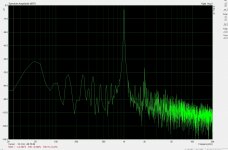
For the HD on picture, it is of the very friendly kind, onevens are quite low except the first harmonic who is -40 dB I have also flip the polarity of supplys on both for using N-fets, or make a symetrical supply for front end so I can drive everything I get my hands on
regards
I have made it test amp with this, the output circlotron has only drain followers and a licht current feedback so it amplifies a little, like a compound amp, so we have a compount circlotron here, however what it does with idle current runout I do not now, because it amplify also the thermal runaway, we need here laterals to prevent.
this amp has only local feedback paths and only current, so for later, I go try this some day.
50 Khz square is oke above that it get worse but it is already very fast on 50 khz, 20 Khz square is already mucho enough, above that things get only unstable.
For the HD on picture, it is of the very friendly kind, onevens are quite low except the first harmonic who is -40 dB I have also flip the polarity of supplys on both for using N-fets, or make a symetrical supply for front end so I can drive everything I get my hands on
regards
Attachments
Last edited:
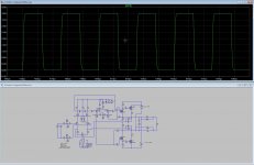
Yet even better is the Sziklai pair make distorting very low.
Here I did use a P-mosfet on the output because of the voltage polarity.
regards
Here I did use a P-mosfet on the output because of the voltage polarity.
regards
Attachments
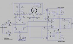
After some pcb making, now some rest and did some hobby simulation, what does a compound circlotron idea I have with a input transformer? I do say this because I have with the present designs a problem with balance, one half of the circlotron is low HD the other is not, reason is the input unbalanced input, when I change this to a transformer input unbalance to balance like this schematic I have no problem with HD, it cancels out nicely.
And sound, ? well, still this time I do not like it, when clipping it is pretty hostile, this is because the long tail pair who normal do amplify is now strengled, killed, making hars sound, what I need here is a follower long tail pair if this excists, I do not now all the amp stuff.
For the transformer version it do well with low distortion, but oke the others had also low hd on sim but not in practice.
regards
Attachments

Some good news, the current feedback do mess the distortion when do drive unbalanced, we need to match the diff parts and we can balance the lpt by change one of the feedback resistors, make one some larger did let drop the distortion below -110 db.
I did make the resistor of one side some bigger, it go to the jfet who gate is earthed that do mess the common mode stuff getting unbalance.
This is worth to investicate so I go do that tomorrow.
the last photo let see when do not change the resistor in unbalance working what it does, a lot more HD, we can also change the 150 ohm resistors on jfet sources in stead of the feedback resistors mentioned..
regards
Attachments


 we get trouble shifting the offset
I have done some changes. the ltp is not involved anymore with the offset adjust, that is een pot now in the vas ltp stage, this way I get not trouble anymore in the ltp input being unbalanced because of that.
I have build a 10 amp 55 volt supply for the circlotron, with that and no lab supply the uneven distortion did drop, left behind only the first even harmonic on -50 dB, what I did see with that supply was a big noise who do golf on screen, I do not now if this is grid noise because here people do grow hennep hahaha.
Oke, the sound of the amp did dramatically improve with the new supply, 2 x 10.000 uF for start, X did mention about a 0.1 resistor in series cap and put another extra in it filtering noise out.
Afcourse I have no current protection now except the fuse, who did die one time with a flash.
regards
kees
Attachments
I have match the 2sj170 mosfets so I can adjust the amp properly, distortion is lower, but need balanced inputs to let it work with lower HD, however the sound is quite oke with the heavy supply, only I get quite a lot interference through the supply transformer a ring core 10 amps x 2 and 42 volts, putting ceramic caps on the rectifiers can help, here the grid is quite dirty, and I have quantization noise from my ac97 output from pc, I think for better measurement I need a M-audio or other audio card.
regards
regards
Attachments

Kees
For OPS lowest output hum&noise make sure that both transformer secondaries are connected in-phase to the asociated bridge rectifiers
Regards
For OPS lowest output hum&noise make sure that both transformer secondaries are connected in-phase to the asociated bridge rectifiers
Regards
Kees
For OPS lowest output hum&noise make sure that both transformer secondaries are connected in-phase to the asociated bridge rectifiers
Regards
Thank you banat, this I did not check because normally it is not needed, I think to put ceramic disks on the rectifiers is a good idea, if the circlotron allow this afcause.
I am very close now to a new setup, I have done now all the different ways on the same board, who afcause is now ruined.
The sound of the casodes and higher voltages give much better sound with balls, the square go easely to 200 Khz and bandwidht in sim was above 1 Mhz, I go limit the amp to much lower values so it is stable, 100 a 150 Khz is fine. HD is below -100 dB but output mosfets are quite important choise for that giving the lowest HD with irfp240 and most bad was the irfp460 (did need high idle) the laterals did also very fine, most even HD and onlt the first and thirth is present. For X it do not fit on a small 100 x 100 anymore, have extra caps for filtering supply on board.
regards
Attachments
Kees
For OPS lowest output hum&noise make sure that both transformer secondaries are connected in-phase to the asociated bridge rectifiers
Regards
For as I did hear with my ears on the box, ehh no in the speaker itselfs I do not hear noise, it is dead quiet.
regards
well , that`s good when amp is death quiet , I guess that you allready have connected main transformers secondaries in-phase to rectifiers , GNFB also suppress hum&noise , but IMHO for top HQ performance everything have to be connected in the right way before GNFB loops are closed ,
be carrefull with 8 ceramic condensers connected as bridge rectifiers snubers since you can get unwanted backward parasitic capacitance which can introduce unwanted capacitive loading to OPS ,
I will try only with let`s say 0,1uF capacitor connected across each transformer secondary .
be carrefull with 8 ceramic condensers connected as bridge rectifiers snubers since you can get unwanted backward parasitic capacitance which can introduce unwanted capacitive loading to OPS ,
I will try only with let`s say 0,1uF capacitor connected across each transformer secondary .
I did measure with the PC, and I did connect the earth of it also on one output, it did blow the fuse. I can even just connect the input signal wire from the pc to the amp output but without a earth connect, it is difficult ot measure the amp in balance this way, a audio card with balanced inputs are needed for that.
I have now two poly capacitors over the amp this do work fine in all amps suppressing bad stuff..
regards
I have now two poly capacitors over the amp this do work fine in all amps suppressing bad stuff..
regards
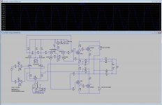
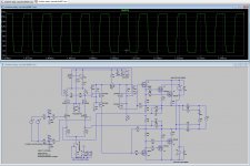
I have done some experiment with a enhanced cascode, and get lower distortions, I do not now wat is best voltages over the mosfets, the top mosfet get now 12 volts and the lower earthed gate has the rest, in the first version I did get 2 volts over the top mosfet or even lower and was in saturation, I do not now if this is alowed in a cascode, I did read about it and have such much info I did not get it properly..
I did read something about a folded cascode however can this be working with mosfets? special in my strange amp, this cascode give more swing and all I get extra is oke with a full mosfet amp.
Last picture is with 4 amps output over 8 ohms and is 32 volts.
X, The irfp460 mosfets did have more then twice the capacitance as a irfp240, more then 4 nF, so I have ordered the irfp240 for testing.
regards
Attachments
Last edited:
- Home
- Amplifiers
- Solid State
- allFET circlotron