Any updates ?
Hi
Yes ia have but sickness of mine mother of 85 do take time, however she is back home again, and it looks we have found the cause (stomach bacteria) and I have started to get in line again.
I am also busy with a welder inverter so I can go on with oldtimer repairs when summer is coming.
I am on 70 % of pcb making of circlotron, and a smps for feeding it with also is coming, but later.
regards
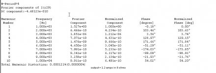
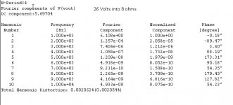
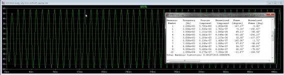
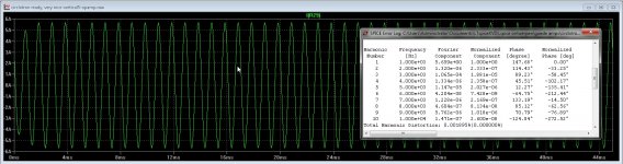
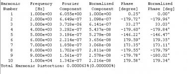
and afcouse the distortion, this is with a 2SK1058 and no autobias, these are lateral mosfets, for me the way to go, for hybrid also because of low capacitance, only 600 pF.
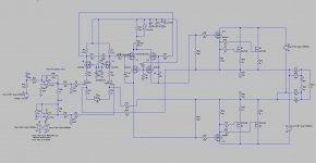
Change of the ZVP and ZVN mosfets did drop the distortion also a lot. so this design can go to PCB .
regards
For this I am also busy to use a input transformer, what do replace the opamps, but using opa627 in it will give high end respons, these are very good opamps..
@Keantoken and @Djoffe where so kind to explane some more about LTspice so I can do a better hd simulation with the amplifier.
Because of capacitance with mosfets the HD above 50 Khz are less good, but that is not a problem.
Now we can go on and implement a multiplier for the bias adjustment and correction.
Because of capacitance with mosfets the HD above 50 Khz are less good, but that is not a problem.
Now we can go on and implement a multiplier for the bias adjustment and correction.
Attachments
Last edited:
The last part is reached, and a question about the idle current runaway compensation, I can use the multiplier who is adviced here, or use a NTC resistor network who is fast.
Maybe someone here can advice or give tips, the multiplier needs to be inverted otherwise with a normal one it get a wrong compensation, therefore I use a extra transistor who was adviced.
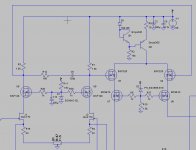
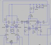
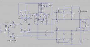
Have two versions, one with hexfets, this one have a extra driver, because it is a balanced amp, output has always x 2 output, therefore the extra driver do drive the big irfp 240 gate capacitance with enough current, and gate has low ohmage resistor to discharge fast, I did get low distortions like you see above.
For the version with laterals, no need of a extra driver, these fets have low capacitance and are special for audio, I do go use these because of the very good sound, but also test the hexfets with the extra driver what it does.
Thanks
regards
Maybe someone here can advice or give tips, the multiplier needs to be inverted otherwise with a normal one it get a wrong compensation, therefore I use a extra transistor who was adviced.
Have two versions, one with hexfets, this one have a extra driver, because it is a balanced amp, output has always x 2 output, therefore the extra driver do drive the big irfp 240 gate capacitance with enough current, and gate has low ohmage resistor to discharge fast, I did get low distortions like you see above.
For the version with laterals, no need of a extra driver, these fets have low capacitance and are special for audio, I do go use these because of the very good sound, but also test the hexfets with the extra driver what it does.
Thanks
regards
Attachments
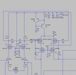
But how to make phase splitter on the input?
The fasesplitter on the input are or opamps or transformer, did think on disctrete opamps, but maybe the present opamp chips are as good special the opa 627 134 etc or a allfet discrete one
Now I need the best way of idle current correction, a positive NTC or VBE with inverter stage because otherwise it do go the wrong way speed up the themral runaway. For me I go make the amp with 2sk1058 because these are for audio and do well in hybrid also, have them in amp who do play already some years here with tube drivers.
The alfet is a idea, maybe it sounds as good or better, so try that is interesting.
regards
Attachments
-
 ScreenHunter_203 Jun. 03 10.59.jpg142.6 KB · Views: 148
 -
 ScreenHunter_204 Jun. 03 11.01.jpg199.2 KB · Views: 114
 -
 ScreenHunter_205 Jun. 03 11.02.jpg127.8 KB · Views: 106
 -
 ScreenHunter_206 Jun. 03 11.11.jpg222.1 KB · Views: 115
 -
 ScreenHunter_208 Jun. 03 11.30.jpg139.2 KB · Views: 129
 -
 ScreenHunter_207 Jun. 03 11.28.jpg216.9 KB · Views: 114
Last edited:
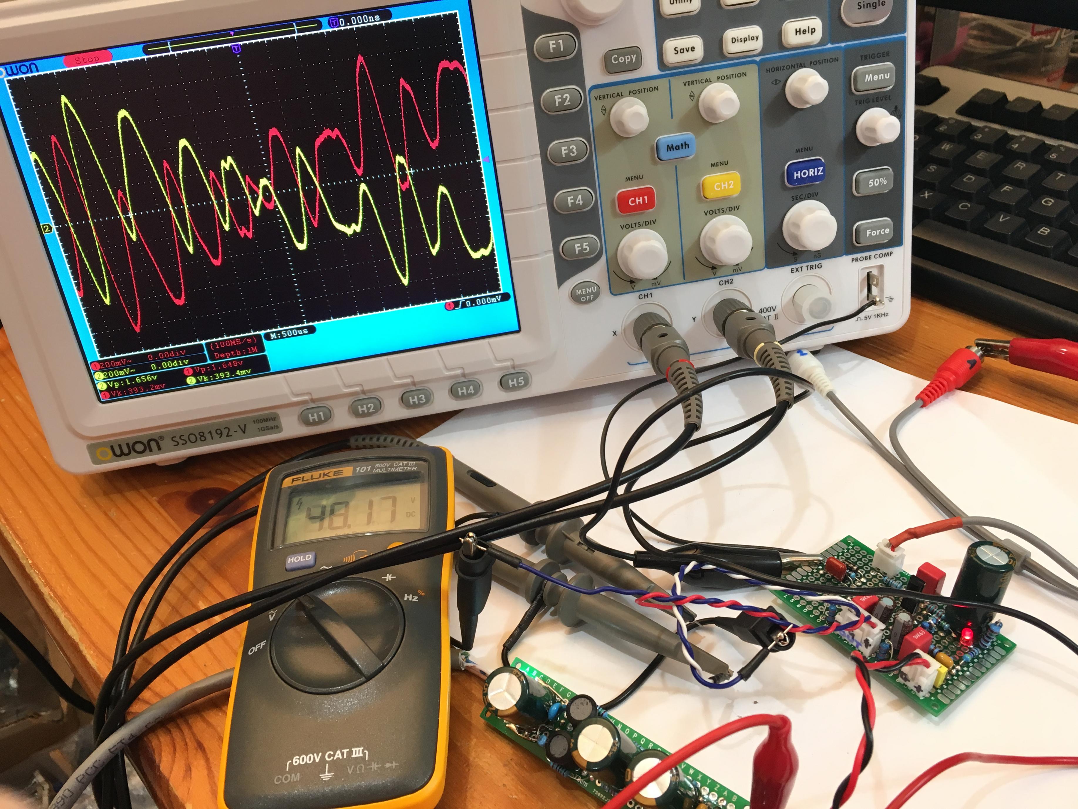
With Aksa's help, I recently made a SE Class A phase splitter with just two transistors. It works quite well to drive balanced drive headphones. Requires a clean 35v to 48v power supply though. I just use 4x9v batteries.
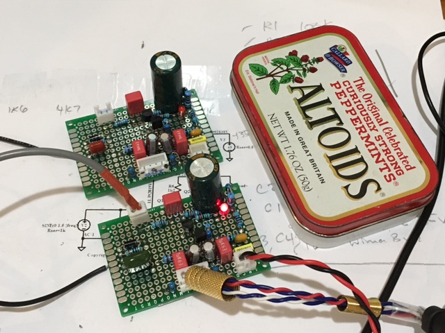
Here, you can see essentially perfect phase splitting with music on the o-scope:
Here, you can see essentially perfect phase splitting with music on the o-scope:
Last edited:
With Aksa's help, I recently made a SE Class A phase splitter with just two transistors. It works quite well to drive balanced drive headphones. Requires a clean 35v to 48v power supply though. I just use 4x9v batteries.
Here, you can see essentially perfect phase splitting with music on the o-scope:
Hi X long time not see, in meantime I had little time to do much because mine mother was hospitalized, but with mine help (good food) and love she is compete recovered, yes the leg's are not good as a result of polio infection in WW2. Oke, I have choose transformer because no extra voltages, I have a version with two opamps burrbrown opa627 or other very high quality but needs voltage.
Two transistors as a fase splitter do give offset voltage as I do use just one supply, so need or a cap, or symmetrical supply.
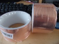
I am busy with the arduino programming a winder, I have also now the copper folie for the earhed layer against capacitance.
In previous post I have let seen the pictures and distortion, I am also busy with class D with multi pole hd distortion correction, one on this forum has schematic to test..
See you have a site and sell amps, that was also a idea of me, I think a good amp will be selled, the hybrid is the most suittable for this, maybe first on a audio meeting
to get a name so people now these are good. But then I need to protect mine designs, or not because it do no harm I think.
regards
Last edited:
Hi Kees,
Great to hear your mum is well now - family before audio of course 🙂
I have no problems using capacitors in the signal path as you can see. I find that 10uF Silmic II's bypassed with a 1uF Wima film works very well and has a sound that I cannot fault. So SE Class A with single supplies is basically all I do nowadays and that's fine because no need for speaker protection from DC, and less expensive simpler PSU's, plus the nice sound of SE Class A.
Cheers,
X
Thank you X
Soon I go start again, mother is oke again, and winter comes, so I do much more inside, first make the winder, then amps.
The woodstove is ready for build so I get warm in winter, this is the most clean woodburnerd there is, sound is very nice, a little
rocketman sound.
YouTube
regards
Soon I go start again, mother is oke again, and winter comes, so I do much more inside, first make the winder, then amps.
The woodstove is ready for build so I get warm in winter, this is the most clean woodburnerd there is, sound is very nice, a little
rocketman sound.
YouTube
regards
Last edited:
Hi Xrk971
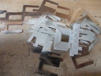
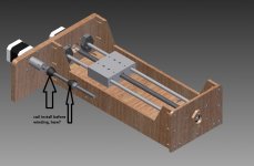
Winter is coming and so I start again with the designs, now I busy with a winding machine, this is a nice thing to use, and so welcome in tools arsenal. I do build a excisting one, no need here to design, and I can not program very wel.
The amp get a transformer in input, that is a more save way for dc errors and make amp simpler.
regards
Attachments
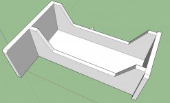
How does the winding machine pictured above work?
This is just the casing, motor and rails come later.
Attachments
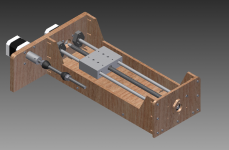

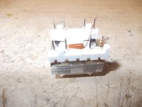
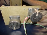
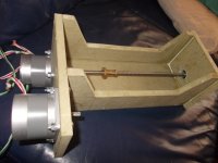
I have now made the case of the winder and install the motor,s.
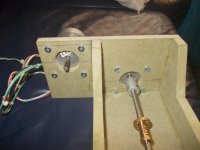
time to make the elctronics to go on however I need this, see last picture or a way to use small transformers on the motor.
regards
time to make the elctronics to go on however I need this, see last picture or a way to use small transformers on the motor.
regards
Attachments
Oke the amplifier has now low distortion, in real that comes after winding the transformer and making the pcb.
Some small parts is still missing for the winder, I think that chinese did not send or lost it on mail.
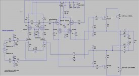
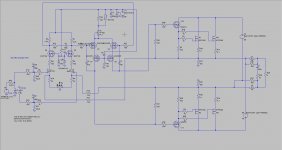
This is the vertcal fet circlotron.
Some small parts is still missing for the winder, I think that chinese did not send or lost it on mail.
This is the vertcal fet circlotron.
Attachments
Last edited:
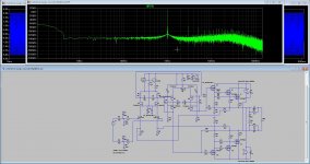
I did again a simulation, this time with a 2sk1058 lateral mosfet, who I think I go that way first, these are made for audio and the thermal runaway is absent.
very low distortion as I have seen. But it is simulation, things can change badly when build it, but it is a good start.
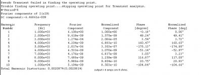
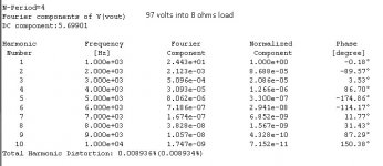
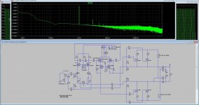
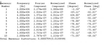
Last picture is 20 Khz distortion, on 50 khz I get 0.089% not bad at all for a mosfet amp who is afcouse capacitive compoments and will do give more distortion on high frequencies, BSP225 mosfet do very well here.
very low distortion as I have seen. But it is simulation, things can change badly when build it, but it is a good start.
Last picture is 20 Khz distortion, on 50 khz I get 0.089% not bad at all for a mosfet amp who is afcouse capacitive compoments and will do give more distortion on high frequencies, BSP225 mosfet do very well here.
Attachments
Last edited:
kees52, do you have already working prototype?
If yes, how it sound?
Hi
Thanks for the attention, I am on this moment busy with class D design and do make a winder for the circlotron, time is a issue because I do work to help people incl mother.
But circlotron get made, I had also more ideas, need to work out because it is more and more difficult to get Jfets, there are very goo opamps these days like burr brown for making a circlotron
but need a revise, think that is interesting also.
thanks and have a nice day/night.
kees
- Home
- Amplifiers
- Solid State
- allFET circlotron