Hi All
I have test the amp and conclusion is sound is nice and warm, measuring distortion with the build in audio card is not, because the circlotron do hang in the air so to speak I need a balanced input, I get high distortion on the pc with arta and when i do remove the load it drops to low value, I do not now if the amp do make the problem or the pc card who is the one on motherboard, ac97 I did see.
I have a sound blaster but this one is not good also.
maybe the feebback do mess things up because I go from single to balanced, however I use diff drivers and input and simulation did give very low distortion with it, but in real it is way high here.
Changing the lab supply for a real supply did not work, unfortanely, same output distortion on load..
thanks
kees
Attachments
Well after read a book, it get some more clear feedback is important as I did now but I have current feedback and the way I did it did modulate the LTP because the resistors are to high, change them in low valeus so there is more current did lower in sim the HD below -100 or -90 with big output power. X using low supply voltage for the front end is a bad idea, I did use 65 volts who did allow cascodes who I always think these sound good and have high linearity.
Have some pictures, from 150 watts and lower, now it is quite clean, and go update the schematic pcb and make it ready.
Alsi I go make a balanced input for hd measuring to the pc, the floating speaker connections need that to measure oke.
Oh I have made the square on 20Khz without overshoots, means the higher region do fall off so amp stays stable, I think sound is also better on that way.
regards
Attachments

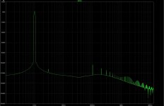
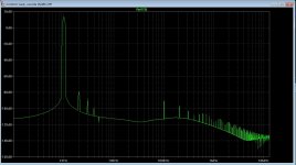
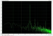
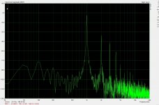
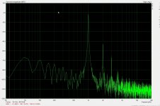
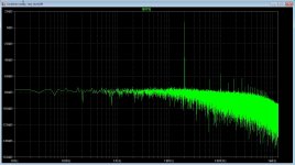
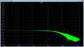
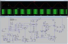
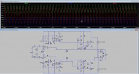
Some more changes who did make the amp better, I do go use lower current sources and symetric supply of 35 volts, this make it better balanced because I get big distortion, the reason I did not see it on simulation was that I did let it sim to short, so change to 1 second and see a lot more trouble.
Now I get with the changes low distortion, I have to say it is on sim, I have not tryed in real time, because the pcb is not yet ready, making it in air wires is to much troublesome.
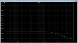
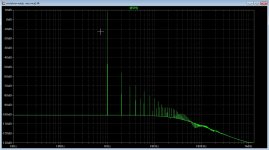
The HD pictures are on 1 Khz, 10 Khz, 50 Khz and 100 Khz, I have put cap,s in vas because of stability problems and it do liniarize the vas with some local feedback making hd better in the HF.
The trouble is because of unbalance of the amp, when using unbalance input it still has higher HD, see last picture.
regards
Now I get with the changes low distortion, I have to say it is on sim, I have not tryed in real time, because the pcb is not yet ready, making it in air wires is to much troublesome.
The HD pictures are on 1 Khz, 10 Khz, 50 Khz and 100 Khz, I have put cap,s in vas because of stability problems and it do liniarize the vas with some local feedback making hd better in the HF.
The trouble is because of unbalance of the amp, when using unbalance input it still has higher HD, see last picture.
regards
Attachments
-
 ScreenHunter_ Dec. 18 16.37.jpg195.4 KB · Views: 100
 -
 ScreenHunter_ Dec. 18 16.34.jpg193.8 KB · Views: 95
 -
 ScreenHunter_ Dec. 18 16.32.jpg203 KB · Views: 98
 -
 ScreenHunter_ Dec. 18 16.43.jpg197.4 KB · Views: 160
 -
 ScreenHunter_ Dec. 18 17.00.jpg180.6 KB · Views: 409
 -
 ScreenHunter_ Dec. 18 17.12.jpg195.5 KB · Views: 99

The distortion is because of the pc card, dc is lifted.
I have record some music through the circlotron amp with the trynergy horn from X as speaker system, it do sound quite well, fine high tones and no hars sound, bass is not really low because of the mobile phone restrictions, so in real it is much better sound.
The K-tube on this horn give a nice result also, with a cheap 19 euro driver.
https://youtu.be/t_fngEFf53s
I do wish everibody a happy and peacefull 2017 and hope the world get to there senses bringing solutions to the country,s where new year is not so hopefull.
Cool design Kees! Looking good - it's getting up there with complexity for high actives count though 🙂
Happy New Year !
Happy New Year !
For class D, when use advanced technology she have future for shure, I have sim a UCD with multiple pole loww pas in singal path a a forward fase correction on coil, it do very nice. and a photo with delta sigma, but this needs a whoooole advanced way of put more ones in it to lower or feed it through a pulse to pwm converter.
Incredible how much people are work on that class D virus, but it is a modulator and as a fm transmitter boy I now what non liniarity is, I did make a demodulator and output as feedback, lowering a 100 mhz radio transmittor HD and very high stereo separation.
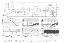
I have made a power comparator schematic in ltspice to see what the article did mention as in photo two.
But maybe in future I do look more, not now, I go make the circlotron pcb.
Incredible how much people are work on that class D virus, but it is a modulator and as a fm transmitter boy I now what non liniarity is, I did make a demodulator and output as feedback, lowering a 100 mhz radio transmittor HD and very high stereo separation.
I have made a power comparator schematic in ltspice to see what the article did mention as in photo two.
But maybe in future I do look more, not now, I go make the circlotron pcb.
Attachments
X
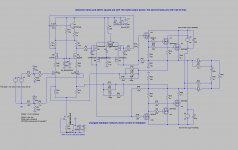
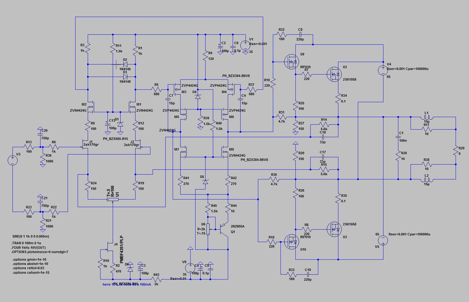
I have made the circlotron more complex because I did need a way to fight the capacitances of the mosfets, with multi cascading I can fight that miller who is much bigger for mosfets and cause TIM stuff.
I go make the pcb, and for supply the front end needs 2 x 65 volts, 350 mA supply, this is because of cascodes and mosfets like higher voltages.
Maybe I go make a smps with the needed voltages.
regards
Wel try again, because sometimes diyaudio do hang for minutes, and lost the text, I have done sims with auto bias schemes, however most are for class A amps and use this on AB do set after it leaves class a go to crossover distortion, however diodes to prevent that it go there do work, I have here tryed it and it looks like it do work, i do now make a setup on the bench to see how wel it do, some comment is welcome afcouse we learn all together from it, I go also setup such a autobias scheme with opto couplers, so it is complete isolated from the circlotron making things more easy, need a optocoupled who can give some more power, a transistor or diodes in it who can withstand 2 amps of so for use it in the driver section, for the hybrid I can use just low power type also.. and opamps to drive them making a kind of automatic pot, or drive with comparator's. making a kind of digital pot.
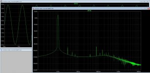
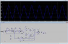
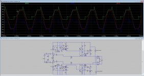
On picture I have one normal output and one clipping, As I do see it well, it keeps in AB class even in clip, that is what we want, idle current was set on 900 mA and automate need only to correct for runaway and keep idle constant the diodes do clip signal preventing that the autobias runs out of steam and get into class c, if I see this right afcouse..
regards
Attachments
Last edited:
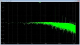
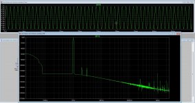
and afcouse the distortion, this is with a 2SK1058 and no autobias, these are lateral mosfets, for me the way to go, for hubrid also because of low capacitance, only 600 pF.
Change of the ZVP and ZVN mosfets did drop the distortion also a lot. so this design can go to PCB .
regards
Change of the ZVP and ZVN mosfets did drop the distortion also a lot. so this design can go to PCB .
regards
and afcouse the distortion, this is with a 2SK1058 and no autobias, these are lateral mosfets, for me the way to go, for hybrid also because of low capacitance, only 600 pF.
Change of the ZVP and ZVN mosfets did drop the distortion also a lot. so this design can go to PCB .
regards
Change of the ZVP and ZVN mosfets did drop the distortion also a lot. so this design can go to PCB .
regards
Attachments
and afcouse the distortion, this is with a 2SK1058 and no autobias, these are lateral mosfets, for me the way to go, for hybrid also because of low capacitance, only 600 pF.
Change of the ZVP and ZVN mosfets did drop the distortion also a lot. so this design can go to PCB .
regards
Kees, this is a very cool one!
I like the idea of cascoding the laterals with the HexFETs.
Cheers,
Valery
Dear kees52m did you test this schem on PCB? Its look very interesting.
And what about schem from post #803 - which is better in your opinion?
Can you attach both simulation files, please.
I have not yet ready the pcb, mine time is limitted because mother is hospitalized, if all good she get home this week. reason, infection with a nasty bacteria who do not respond to antibiotics well, this is a danger for us, and big pharma do not develop new ones because it do not bring enough mony, what a shame in the west, mother is 85 so quite breakable. .
Oke back on circlotron, I go sim and post.
Hi Valery,
Where is the lateral being cascoded? The BSS192's are verticals aren't they? I also look forward to Kees finishing the next gen design. The first one, although a good test bed, is not a PCB I can make work like Kees can.
Where is the lateral being cascoded? The BSS192's are verticals aren't they? I also look forward to Kees finishing the next gen design. The first one, although a good test bed, is not a PCB I can make work like Kees can.
Dear kees52m did you test this schem on PCB? Its look very interesting.
And what about schem from post #803 - which is better in your opinion?
Can you attach both simulation files, please.
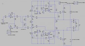
The design in post 803 is no more, did delete it a whyle ago because the simpler the better, and did have also lower HD .
the last one is where the pcb do make for, for the verticals I busy now with a autobias, and that is not so easy, this sample and hold example is what we need, sample ad the crossover region, however auto is not a single sinusoidal of one frequency but complicated siusoidal signals.
regards
Attachments
Hi Valery,
Where is the lateral being cascoded? The BSS192's are verticals aren't they? I also look forward to Kees finishing the next gen design. The first one, although a good test bed, is not a PCB I can make work like Kees can.
BSS 182 are verticals indeed but there are much others also like the nice bsp225.
Hi Valery,
Where is the lateral being cascoded? The BSS192's are verticals aren't they? I also look forward to Kees finishing the next gen design. The first one, although a good test bed, is not a PCB I can make work like Kees can.
X, you're right - I assumed laterals in those positions by some reason 🙂
Anyway, overall topology looks very good to me.
- Home
- Amplifiers
- Solid State
- allFET circlotron