Joe and X and Banad.
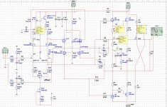
Have you guys also tought about this way to solve the extra supply?, a current mirror and a resistor do very well, as the sim wil let me believe that is.
HD is very very low with it and feedback lines are of invloence of the whole now.
Hd is 1 Khz and 100Khz, amp the extra driver version, who do have the best papers
You need higher supply if you want have efficienty left, but maybe a small class a amp can be done with low voltages,..
regards
Attachments

Last edited:
It's been a while since I played with this type of approach, but as I now recall, the thing to watch out for is power supply noise on the output. It's best to check with the actual power supplies you plan to use. You may want to look at that before taking the idea further.
It's been a while since I played with this type of approach, but as I now recall, the thing to watch out for is power supply noise on the output. It's best to check with the actual power supplies you plan to use. You may want to look at that before taking the idea further.
A low drop regulator in the +supply?.
I have now the amp on plus and minus 35 volts on a 500 mA supply, but this do not work with this aproach as it needs reference
except when we do a symetric supply, who by the way is not that diofficult these days and the insolation do make sound happy.
regards
Last edited:
It's been a while since I played with this type of approach, but as I now recall, the thing to watch out for is power supply noise on the output. It's best to check with the actual power supplies you plan to use. You may want to look at that before taking the idea further.
Joe
I think it is better for the stability to use two separate supplys, for the driver 500 mA to 1 amp and for output the 5 oe 10 amp version.
These days it is cheap to make a supply and also the supply noise is far away when stabilize the driver supply, for example a gyrator.
This aporach however can be implemented with a total balanced amp, who I have.
regards
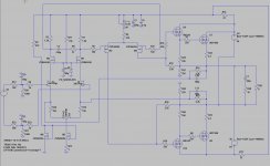
Oke, as known I do not give up easely, I try just all I do think off, just get a grab in the magic box who a amp is.
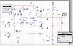
Have now make a negative with two 1N4003 diodes, need these because of the current what go through it with the ground reference resistors, two diodes and a big cap do remove the sinusoidal there so we have a clean -1.5 volts, enough for the PN4392 who do very wel there, and get rid of temp trouble.
So Joe, what you think, I have a version with a own supply and one who use the circlotron supply. to remove the supply noise this regulator is maybe idea, this noise is
not present when use a own supply, now we need just one plus Voltage, I did use 65 volts, and sim on 50 volts, the amp is very clean in sim.
regards
Attachments


In some ways it's easier to get good performance from separate front end and output supplies, and that is why I use them. But I've always thought it would be nice to have a simpler power solution, as it might make a more attractive DIY project. For me, it's more about taking complexity out of the project than cost, although lower cost is also attractive.
In some ways it's easier to get good performance from separate front end and output supplies, and that is why I use them. But I've always thought it would be nice to have a simpler power solution, as it might make a more attractive DIY project. For me, it's more about taking complexity out of the project than cost, although lower cost is also attractive.
These amps are low cost as I see the parts, using the most easy to get ones.
For the balanced version these did not be such forgiving, it needs a own supply to stay stable without offset modulation effects, the speaker do then wibble when give some more power because offset do change with bass frequenties.
With a separate driver supply this do not happen, I have test.
The present amplifier do very well with sound, have almost the same sound as the hybrid, and the idle current do go 100 mA up when cold and then drop to 500mA when very hot (bake an egg ), so this is very nice, starting with higher idle is not a problem, it helps warming up also but when using a fan then it stays higher so adjust back to 500 mA.
I have also used cascodes, I do like them because of high open loop you get with just one stage, so making it very liniair with the feedback. Also
the capacitance is mucho lower for the LTP, who do then also distort much lower, all do nice.
The amp I now working on with the driver who do drive the power fets without a source follower was the present amplifier mentioned.
The diode for making negative I do like, it make the supply easyer and can also be coupled on the circlotron supply for easy making.
regards
Last edited:
The diode for making negative I do like, it make the supply easyer and can also be coupled on the circlotron supply for easy making.
It can work well, and this was actually the way I built my first circlotron front end supply. My concern about noise has more to do with the amount of power supply noise on the output lines in the case where you take the B- for the front end from the output supplies. In doing this, you in effect place a voltage divider across each of the floating supplies, which divides both the supply voltage and its noise above and below ground.
In my last example above, I made a B- by splitting the 35V output supply voltage roughly 4:1, so about 25% of the total supply noise would appear on the B-. For a supply having 400 mV noise, that would mean a B- with about 100 mV noise. This can be easily filtered out of the front end B- supply, but it stays on the output because the negative side of each floating supply is tied directly to one output terminal.
However, the problem here may not be so bad after all. This amplifier uses global negative feedback, which should reduce output noise by at least a factor of 10. In addition, the supply noise is largely the same on both output lines, so most of it cancels across the load. Allowing another factor of 10 for that gets you down to 1 mV, which (if my math is right) is about 67 dB below 1W/8 ohms. I've made amps with this much noise and they actually sounded pretty quiet on 86 dB efficient speakers.
For general applications, I'd rather see the noise down at least another 10 dB. Better filtering of the floating supplies is probably the best solution. Using a CRC filter on the output supplies and snubbing the secondaries should achieve this, and also help ensure that the remaining noise is at lower frequencies where it is more effectively reduced by global feedback and cancelation across the load. It also helps to use as little B- as you can, because this leaves a smaller percentage of the total supply noise on the outputs in the first place.
Hi Joe
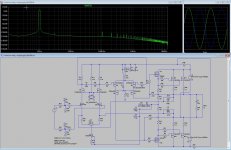
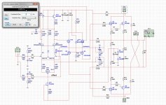
The diode version do NOT sim in multisim, it is very unstable there, and with LTspice all is fine and do sim well, I agree multisim is not the best software, possible the metering and oscilloscope do make trouble.
O yes Joe, the cascodes after the LTP has a zener, I have did set on 6.8 v id do not adjust current, when set on 10 volts it does, have you idea what is the best setting of that diode, because do the math, is not my thing.
For the diode string, I go not the way of putting circlotron supply in work, I go for a separate one, this is much better and stable then use the circlotron, and the pcb making get more complicated with reaces who go over board from left to right.
I put a extra resistor on the supply for the front end so the current trough the diodes is more stable.
The present version is stable now what concerns the idle current, with 0.1 ohm source resistors and a mje350 with 47 ohm degeneration resistor keeps the amp idle between 500 and 530 mA from cold to extreme hot (not touchable) with a Vbe on ltp top, that works very good.
The new version will have the extra driver, and see what happens in real time, that way on liniair distortion because of miller is avoided as what happens with the first one where ltp drives a power mosfet with 170 pF what will be multiplyed because this driver do amplify, I can also use a cascode here with two extra irf9610 mosfets who remove that miller, and can drive current to the mosfets.
On picture the first one is with multisim, you see that strange voltages, the other are ltspice who do well, no problems so what is trustable.
regards
Attachments

The diode version do NOT sim in multisim . . . On picture the first one is with multisim, you see that strange voltages, the other are ltspice who do well, no problems so what is trustable.
I don't use Multisim, but in your picture I see two different symbols used for ground. Are they electrically the same? If not, I imagine that could cause problems.
I don't use Multisim, but in your picture I see two different symbols used for ground. Are they electrically the same? If not, I imagine that could cause problems.
The symbols are or eu or usa versions, but I try, good tip.
U has right, now I understand why some schematics did so wrong, I get to keep same parts, All EU or US.
For sim he separate supplys do best, the diode and the PN4392 or 4391 Jfet in the CCS do work fine, the PN4391 sits now also in mine and has no temp sensitivity anymore, the idle stays within 500 mA plus and minus 20 mA, that is nice. I have use a extra resistor who take some mA away in driver section so both diodes get more stable, good Idea?.
For the extra driver amp, I go start the pcb, I have enough simmed now, also other things to do.
thanks.
Attachments
The word Circlotron was used long ago for tube amps
This All FET design is quite clever. I wonder if people are aware, the term Circlotron originally was used for an amplifier in the tube era. It is attributed to Cecil Hall in US Patent 2,705,265, June 7, 1951. It achieved modest commercial popularity in the mid 50s. One key benefit was doing away with the output transformer in some implementations, resulting in a elimination of the performance limitations of the output transformer and huge savings in cost and bulk.
https://en.wikipedia.org/wiki/Circlotron
Circlotron History
There was a patented solid state version early in 1959:
http://www.tubecad.com/2008/03/25/A.W. Donald III-SEMICONDUCTOR_AMPLIFIERS.pdf
This was followed by many improvements. The concept lives on in many current product designs using tubes, solid state or some combination of both.
Aikido PP & Solid-State Circlotron
Schiit Happened: The Story of the World's Most Improbable Start-Up - Page 73
Circlotron AMPLIMOS one stage amplifiers
Ianus Monaural Hybrid - Aries Cerat
It's amazing how a concept can be invented, go obsolete, be resurrected and then touted as novel. As the song says, everything old is new.
Hi Slowhands
Thanks for the info, I do now amplifiers of the analog class has already be out rechearched, but the combinations of all that stuff not, but soon we get digital, promissing maybe, special when make a Triangular-Wave with a processor to get it extreem liniair for that digital amp dropping hd very much.
But I am more a liniair amp man, so we go here.
Joe.
This one I go make pcb for, it is the best working version.
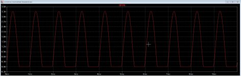
Get -100 dB hd on 150 watts.
regards
Thanks for the info, I do now amplifiers of the analog class has already be out rechearched, but the combinations of all that stuff not, but soon we get digital, promissing maybe, special when make a Triangular-Wave with a processor to get it extreem liniair for that digital amp dropping hd very much.
But I am more a liniair amp man, so we go here.
Joe.
This one I go make pcb for, it is the best working version.
Get -100 dB hd on 150 watts.
regards
Attachments
This one I go make pcb for, it is the best working version.
The only other suggestion I have for now is to remove the gate resistors from M3-M4 and U9-U10 and place them instead on M1-M2 and M7-M8. The Pass/Thagard A75 article (Pt.1) on www.passdiy.com nicely explains how and why to use these resistors.
The only other suggestion I have for now is to remove the gate resistors from M3-M4 and U9-U10 and place them instead on M1-M2 and M7-M8. The Pass/Thagard A75 article (Pt.1) on www.passdiy.com nicely explains how and why to use these resistors.
Hi Joe
I go read there.
The gatestop resistors are there to prevent oscillations, but maybe you are right about where to pu them..
The most distortion I have with the present one is because of the LTP high impedance drive a miller mosfet who do almost all the amplification, and I do generate much harmonics because of this capacitances, but with all amplifiers we have to look at miller, that is why the new one has cascodes, I can put two extra mosfets also in the present one removing all the capacitance who is generated by amplification, like two small 100 mA mosfets who do drop just 1 volt or so and the grounded gate mosfet do all teh amplification, like I did with the new one who as also a extra source follower driver in the circlotron with low capacitance, that is why it works.
I do see on sim when drive the amp to limits it get negative, but negative is just 1.5 volts so it clamps to it, that is not nice, so a higher negative voltage prevent that? It has to swing between the positive voltages, but to get circlotron mosfets working it is set on 4.2 volts idle and swings then up and some part down, there it clamps with earth as we get high power, I need to set idle current high to prevent, because it makes headroom larger, this is not with the new extra driver version, these swing is oke because it is removed from supply or earth egde... If I explane ith oke with my limited english.
Read some on the article, he uses normal mosfets in the LTP stage, and not jfets like me, so he can drive more current, maybe a nice idea for the input stage of the first design circlotron, to drive the mosfets with the miller problem, miller cause IM and that is nasty distortion generating also oneven HD.
regards
Attachments
Last edited:
I do see on sim when drive the amp to limits it get negative, but negative is just 1.5 volts so it clamps to it, that is not nice, so a higher negative voltage prevent that?
You might try lifting the junction of R20-R27 off of ground and connecting it to your B- through a 150 ohm (or so) resistor. Can you see if that helps? More B- might help your LTP CCS work better, but if it was working before, I wouldn't change that yet.
Hi Joe
The tests are here.
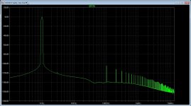
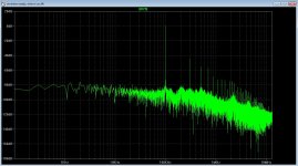
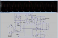
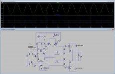
Little confusing but I think it works fine with the extra driver, but also the single olde version do well, the negative he gets from the circlotron output, when put R31 and R30 on ground it clip in the negative side when get to much swing, when connected to circlotron it go negative fine, so it needs te be connected there.
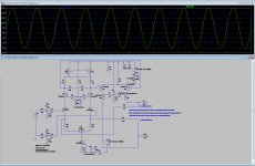
You see on last picture it clips already with low output swing, but when together with circlotron it do work fine with high swing as in precious post, I think because the circlotron do help with netagive swing capability pull driver down with it.
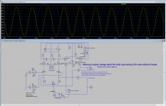
You see also on one picture that without circlotron stage and put driver onhalf voltage I get uge swing, but circlotron itselfs do need 4.5 volts from negative to work, maybe a drain follower or a compound stage circlotron do let it be higher.
regards
The tests are here.
Little confusing but I think it works fine with the extra driver, but also the single olde version do well, the negative he gets from the circlotron output, when put R31 and R30 on ground it clip in the negative side when get to much swing, when connected to circlotron it go negative fine, so it needs te be connected there.
You see on last picture it clips already with low output swing, but when together with circlotron it do work fine with high swing as in precious post, I think because the circlotron do help with netagive swing capability pull driver down with it.
You see also on one picture that without circlotron stage and put driver onhalf voltage I get uge swing, but circlotron itselfs do need 4.5 volts from negative to work, maybe a drain follower or a compound stage circlotron do let it be higher.
regards
Attachments
Last edited:
[T]he negative he gets from the circlotron output, when put R31 and R30 on ground it clip in the negative side when get to much swing, when connected to circlotron it go negative fine, so it needs te be connected there.
That is correct. In this design, the floating supplies provide the negative swing, and the B- is only needed (if at all) to provide operating voltage for the LTP CCS.
For me, it helps to think about this type of amplifier as a set of closed current loops. All current flowing from each supply must somehow return to the same supply (Kirchoff's current law). Pay attention to the paths through which that happens, and remember that, in this context, ground is just a reference, not a destination. 🙂
Joe
We just use the reference resistors. I had some doubts about what happens and so on, I can design amps but the theoretical math path is not my thingy, I do combine, that is why simulation these days is such a God,s gift.
But then still afcouse I need some intelligence to do, and ask people here for advice.
So Joe and X have also kick in some chromosomes for this new idea based on old thinking.
The abcense of miller (cascodes) and high capacitance for the ltp did change things. I have also look at a LTP who can kick balls, like it does in pass labs, worth a try my way combinings.
regards
- Home
- Amplifiers
- Solid State
- allFET circlotron