Kees
IMHO to thermally stabilize Circ.OPS ...
-insert appropriate source power resistors for IRF460 ,
- insert two appropriate values NTC resistors , each directly soldered in-between source and gate of each IRF460 , those NTC`s must have very good thermal contact with IRF body`s .
ps , try to replace that thermally unstable JFET-CCS with just single one appropriate value simple resistor and see what`s happen .
Best Regards
Hi Banat
I am trying now the Joe mosfet Vge approach, the power resistors in series with sources is a good idea because maybe this is only needed, the driver vas do help lowering idle, but in a smal tem area, for as X want class a 1,3 amp, we need or a active aproach like a servo with a opamp or a quick sensor right on the mosfet body.
I did see a amp who did use ntc,s but these can not have much load, I though the pass amp did use it as X say, maybe worth a try.
regards
Hi All. I think we need a change, because the driver works to drive mowfets directly give a probleem with themperature, possible because of the high idle for class A driving and drain follower who amplify making things worse, it jumps two sides and is almost not trackable, with a NTC in the LTP upper side with diode parallel did the best, the joe approach did work also but then I run out of idle steam getting crossover when hot, so overcompensates.
I propose a extra driver in the cirlotron, and let the vas work on low idle, and not on heatsink making temp things much more stable, two ntc are used on both sides of the circlotron driver gates to source and tune with series resistor as a part of adjustment.
The distortion is very low with this approach, and I have cascoded the high end part to circlotron so I have no miller problems with ltp and things get much more liniair because of low gate capacitance.
I have two versions, one with 4 x 2sk1058 or 2 x irfp460 and the ntc.
Joe, your schematic I have simmed, it do give higher HD, I did not get it low, I do not now if the new approach will do but I have trust in the two ntc on the right place for fast corrections. Your temp sensitive CCS I have now under test do overcompensate, I have for as in class a 1.3 amp idle need a sensor very close to the die of the irfp460 or 240 can be done with a to92 in a hole through heatsink under the die of the mosfet who will then act very fast.
The 2sk1058 give higher HD, however it are only even ones making it a friendly amp for audio.
regards
Attachments
-
 ScreenHunter_ Oct. 22 14.49.jpg167.2 KB · Views: 212
 -
 ScreenHunter_ Oct. 22 14.11.jpg188.2 KB · Views: 204
 -
 ScreenHunter_609 Oct. 22 13.33.jpg31.6 KB · Views: 187
 -
 ScreenHunter_ Oct. 22 13.29.jpg120.1 KB · Views: 187
 -
 ScreenHunter_ Oct. 22 14.39.jpg177.3 KB · Views: 203
 -
 ScreenHunter_ Oct. 22 14.31.jpg191.4 KB · Views: 99
Last edited:
Joe
your temp controlled ccs do work now, I have to degenerate the sense transistor by using a 220 ohm in series, and lower the 47k resistor to 4.7k. also the sense transistor
is fitted on the power fet house doing it on the heatsink it do run out, this is because of the vertical mosfet has such a extreme transconductance, some source resistors as banat
mention is a good idea.
X this do work for class a but then you need to put a sense transistor through a hole in heatsink under the bottom of the irfp250 so die can be measured directly, I think this is a normal aproach needed for 1.3 amps idle.
'The Joe approach do keep now the amp in 500 a 550 mA between 25 and such heat I can barely touch heatsink , so this extreme test is succeeded.
I do like more to use mosfets, Joe mention this can used, can you please then give a schematic idea, I have try but not succeed.
I think a normal Vbe as a voltage source work even better with a extra pnp to get positive respons, maybe worth a test.
Man what a school, I learn a lot this way😛
Thanks.
kees
your temp controlled ccs do work now, I have to degenerate the sense transistor by using a 220 ohm in series, and lower the 47k resistor to 4.7k. also the sense transistor
is fitted on the power fet house doing it on the heatsink it do run out, this is because of the vertical mosfet has such a extreme transconductance, some source resistors as banat
mention is a good idea.
X this do work for class a but then you need to put a sense transistor through a hole in heatsink under the bottom of the irfp250 so die can be measured directly, I think this is a normal aproach needed for 1.3 amps idle.
'The Joe approach do keep now the amp in 500 a 550 mA between 25 and such heat I can barely touch heatsink
, so this extreme test is succeeded.I do like more to use mosfets, Joe mention this can used, can you please then give a schematic idea, I have try but not succeed.
I think a normal Vbe as a voltage source work even better with a extra pnp to get positive respons, maybe worth a test.
Man what a school, I learn a lot this way😛
Thanks.
kees
Last edited:
It's a cement filled white ceramic one - rated 10w I think. I have a proper 25w aluminum cased one mounted on a heatsink resistor I could use for long term testing.
I don't know how different IRFP250's are. I will switch to Digikey sourced IRFP240's tonight and see if that helps. I will also add BD139 temp compensator.
It's fun and I learn a lot more when an amp doesn't work the first time.
I wonder if 0.33R Supply resistors on IRFP pins leading to driver would help? Maybe that would dampen oscillations if that was the source?
Hi X
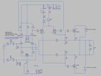
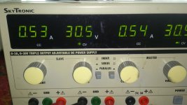
He is stable now, stay between 480 and 540 mA in the whole temp range of household to very hot I can not put hands on or just one second. That is good
sign, schematic is included wehere it works, the BD139 is on irfp460 housing under the screw, turn it in line of the middle pin of 460 mosfet. If you want A class, we need a very tight connection to die of the mosfet, so the bottom, or glue a small smd transistor on the source pin next to housing.
amp is stable, no oscillations, so build it this way works, however need pcb correction. or moount the temp correcting CCS above for temperary testing, I think I go for a new pcb and build the one with the extra driver in circlotron, this give mucho better respons. we can seperate circlotron and driver on separate boards.
Just try this corrections, it do work. amp do now run long term, to see what happens, as I now see it is thermally stable.
regards
Attachments
Can you make detailed drawing of board layout showing changes. There are quite a lot of changes I see.
Hi X
I think we need even other pcb, and I have still also the non feedback version and a board
for it to see how that sound lateron.
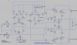
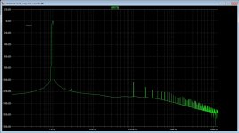
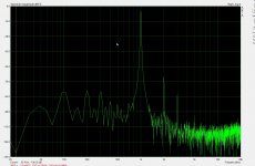
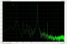
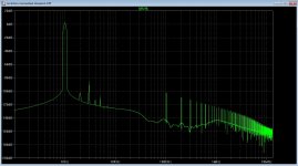
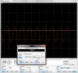
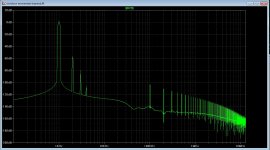
Here some pictures, I do see on this amp the thirth harmonic is stronger then the rest, this is because of it is balanced and has a diff amp input and vas.
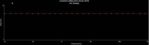
Did some measurements on arta.. compare with sims.
regards
I think we need even other pcb, and I have still also the non feedback version and a board
for it to see how that sound lateron.
Here some pictures, I do see on this amp the thirth harmonic is stronger then the rest, this is because of it is balanced and has a diff amp input and vas.
Did some measurements on arta.. compare with sims.
regards
Attachments
Last edited:
Kees
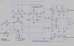
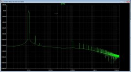
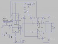
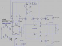
If you interested in GNFB-free amp than check this two schematics ,
first one is with BJT front end , notice those two 10K resistors inserted for local neg.feedback around Circl.OPS ,
second one is your schematic but also with applied local negative fdbck(Shade) around OPS .
regards
If you interested in GNFB-free amp than check this two schematics ,
first one is with BJT front end , notice those two 10K resistors inserted for local neg.feedback around Circl.OPS ,
second one is your schematic but also with applied local negative fdbck(Shade) around OPS .
regards
Attachments
Kees
If you interested in GNFB-free amp than check this two schematics ,
first one is with BJT front end , notice those two 10K resistors inserted for local neg.feedback around Circl.OPS ,
second one is your schematic but also with applied local negative fdbck(Shade) around OPS .
regards
I have a design who is local feedbacked with degeneration resistors and do nicely.
I have the idea to redesign the pcb and schematic with the extra driver version, I go as last resort try a current mirror in ltp top to see what it does with the oneven harmonics and also a cascode in the VAS part to fight miller who do make HD more worse.
X you can listen to the amp here on youtube who belong to the schematic included.
https://youtu.be/tJZ6AkIsH-A
regards
Attachments

Banad
Here I have a schematic who has not overall feedback path but local, and have low distortion anyway but need higher supply voltage like 65 volts for preamp for enough swing, who is for all amp needed when high power demands.
And the last two are the extra driver sersion and this has the lowest distortion but is current feedbacked.
regards
Attachments


X
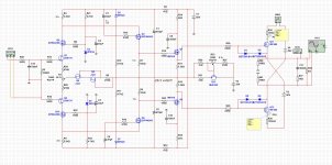
I have put in two extra fets so we have a cascoded driver, this do make the HD a lot more music friendly I do see on sim.
the small fets with small capacity do not load the LTP, and miller is not present anymore who I do tell make trouwble with HD, special with mosfet capacity.
regards
I have put in two extra fets so we have a cascoded driver, this do make the HD a lot more music friendly I do see on sim.
the small fets with small capacity do not load the LTP, and miller is not present anymore who I do tell make trouwble with HD, special with mosfet capacity.
regards
Attachments
X
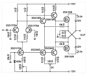
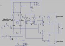
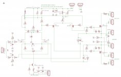
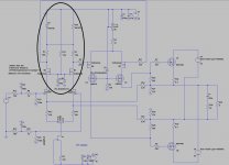
Here is the amp schematic, I am busy with the last part, and is the temco implementation.
The mosfets urfp240 needs the sensor very close to the die, maybe glue the ntc on the body or better sense the source pin who give through heat very fast.
I go now try that and use a ntc in series with top of the LTP, this way the current through it will not be altered, only the voltage to gates of vas, with a max of 0.6 volts, (diode).
How it sounds you can listen here, with drums and percussions, the amp let see it is extreme fast, it hits powerfull, but amp do has a rocky character, this is due to oneven harmonics are present, that is why I go over to the version with casocdes, and a extra driver, I go for myself use lateral mosfets because of very low capaciatnce of 600 pf in stead of 4200 pF who introduce all kinds of products when not driven properly. But as I say, it is taste what sound oke or not, diff amps do introduce oneven harmonics but it do not say it is bad because I have only single second and thirth ones and not higher up.
But amp is simple now, when I am ready with ntc I give all valeus to you.
regards
Attachments
Last edited:
PCB making.
https://nl.aliexpress.com/item/10-p...Fabrication-L-10cm-W-10cm/1722846390.html?s=p
Send to you from my own country is mucho cheaper.
https://nl.aliexpress.com/item/10-p...Fabrication-L-10cm-W-10cm/1722846390.html?s=p
Send to you from my own country is mucho cheaper.
very nice to put the amp in.
https://nl.aliexpress.com/item/NEW-...chassis-AMP-box-with-heatsink/1681682167.html
https://nl.aliexpress.com/item/NEW-...chassis-AMP-box-with-heatsink/1681682167.html
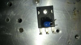
I have made a picture how the ntc be mounted, on the source pin who give heat through very fast, gleud on of use a scrink socket is maybe a better way.
Now it can react super fast on temp changes who is usefull for class A duty.
It is important that the both circlotron mosfets are mounted such that temp variations are as close as possible, so use a insulators of same manufacurer or specs.
regards
Now it can react super fast on temp changes who is usefull for class A duty.
It is important that the both circlotron mosfets are mounted such that temp variations are as close as possible, so use a insulators of same manufacurer or specs.
regards
Attachments
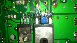
Now the ntc sits on the body, with superglue, it was to big for the pins, two compenents glue is the future way.
This way the temp tracking has to be good, tuning the temco is last resource, then it is compensated and ready for a updated board, in my case with extra driver and some changes but compensating for temp is the same. NTC work fine and is fast and simple.
regards
This way the temp tracking has to be good, tuning the temco is last resource, then it is compensated and ready for a updated board, in my case with extra driver and some changes but compensating for temp is the same. NTC work fine and is fast and simple.
regards
Attachments
My NTC looks like a glass body diode. 4.7k nominal value and is much thinner and easier to mount I think.
very nice to put the amp in.
https://nl.aliexpress.com/item/NEW-...chassis-AMP-box-with-heatsink/1681682167.html
That's a nice case but I think primarily for headphone amps as heatsinks are on small side.
My NTC looks like a glass body diode. 4.7k nominal value and is much thinner and easier to mount I think.
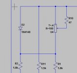
We need 200 ohms NTC, and a diode in series with series resistors on top of ltp, this way the current through the ltp do not be altered because the ccs below keep it constant,
only the voltage on gates of VAS do change who is fine, diode makes a max voltage change of 0.6 volts.
I have now quite stable idle, even at 1 amp, but when use a ventilator when amp is hot to cool down just do not blow over the pcb and the power mosfets, local cooldown is not correctable, but this is also not the meaning to do that, when collong down only the heatsink ot work fine.
The schematic on last picture is who we can tune the NTC with a pot, for example when in class a, but need tight connected to the power mosfet, the source pin is a nice place, close to the plastic.
Have you listen to the music? because I do not hear from you how it sounds to you>,
regards
Attachments
Last edited:
I presume it do not sound well.
I have started a new design, with lateral mosfets because I like this mucho more, has a extra driver also in circlotron because this way it do well with HD.
The present design do also quite oke, but sound is a more english character.
Still, the hybrid tube mosfet is not yet beaten qua sound quality.
regards
My NTC looks like a glass body diode. 4.7k nominal value and is much thinner and easier to mount I think.
4.7k is to much for the present amplifier, here I do use a 200 ohm type, and a tune pot to adjust temco.
it did overnight keep idle within 50 mA, but start higher who is not so bad because that way the mosfets warm up fast, but also heatsink has impact afcouse.
Where X did you buy that bag with insolators?
- Home
- Amplifiers
- Solid State
- allFET circlotron